 [1]Engine assembly is one of those processes that understandably terrifies a majority of the DIY-type enthusiasts out there, and for good reason. You’re piecing together the heart of your engine, where components are rotating hundreds of times per second with engine bearing and other clearances being measured down to the thousandths and even tenths of a thousandth of an inch in some cases! Needless to say, accuracy and patience are of the utmost importance here.
When installing main engine bearings and connecting rod bearings, following the correct procedures will reduce excess wear and friction to guarantee a long and healthy life for your engine’s rotating assembly. For those of you who are all-in on doing this yourself or are just curious to learn more about what is involved — King Engine Bearings has created a simple twelve-step installation guide [2] for rod and main bearings!
In this article we’ll be going over a few of the major steps covered in King Bearing’s guide and diving a little further into each topic.
 [3]
[3]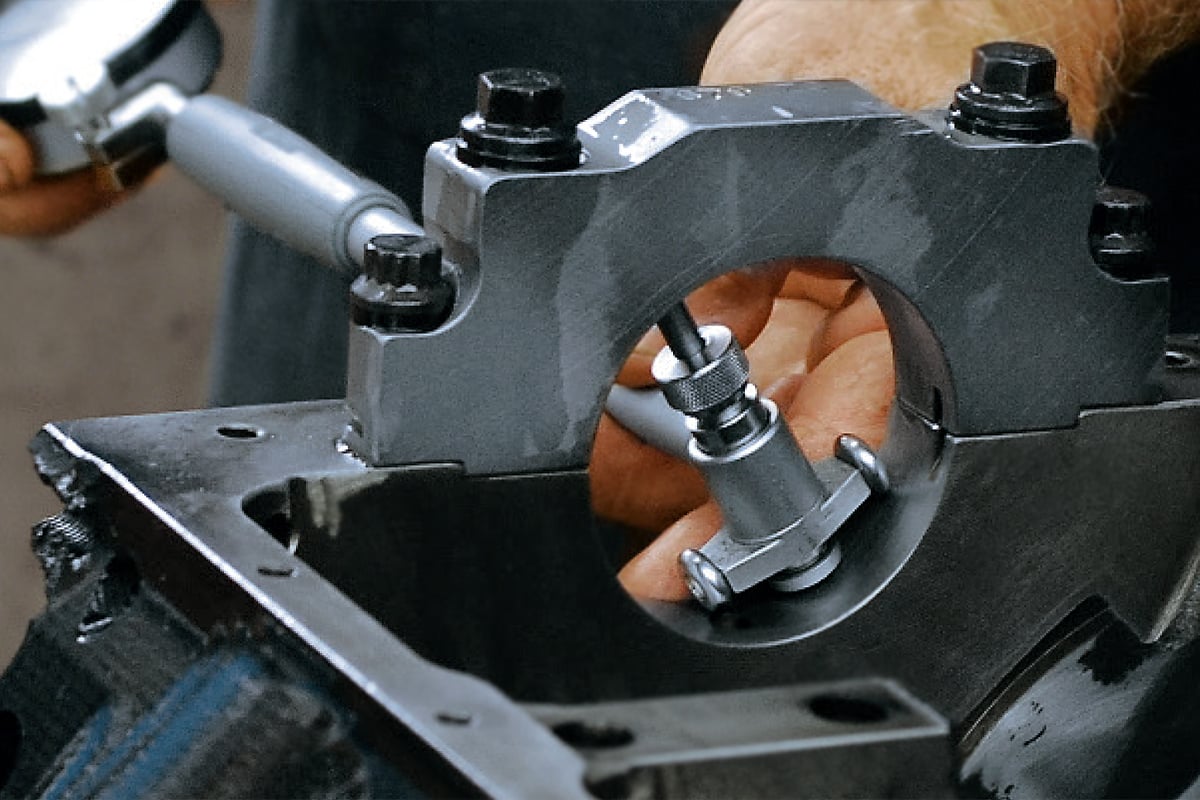 [4]
[4]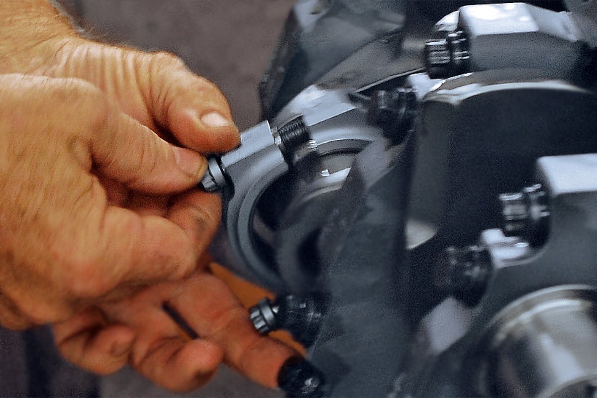 [5]
[5]
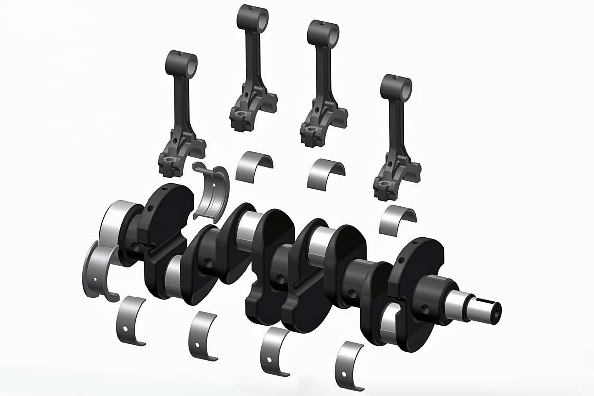
Matching Caps
One of the most critical steps (and the first one mentioned in the guide) that many enthusiasts may not even realize the importance of is making sure that each connecting rod and main bearing cap is properly identified by position and orientation.
This is because each cap is perfectly machined to match the mating surface of the block as well as the shape of the bearing bore itself. If the proper precautions aren’t taken to identify each cap to be sure that they do not get mixed up, excessive bearing and journal wear will occur and possibly even severe engine damage.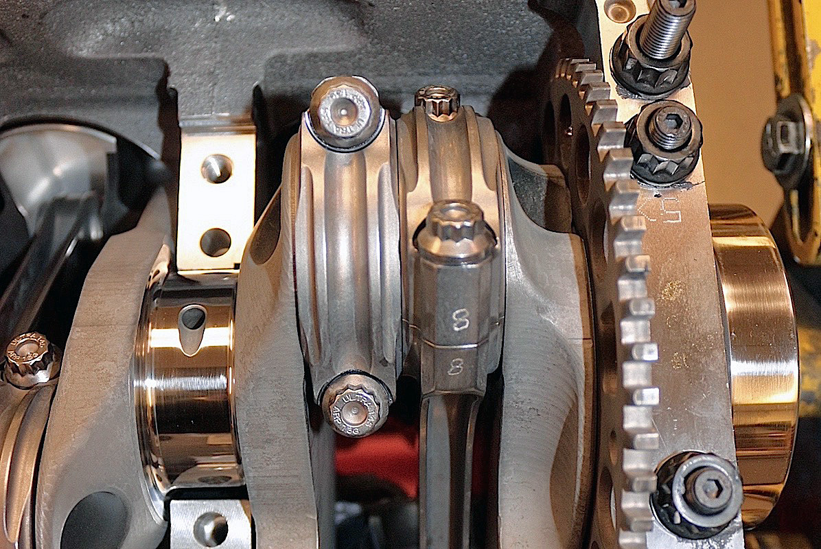 [6]
[6]
Keeping It Clean
Keeping surfaces clean, such as the crankshaft, engine block mating surfaces, and journals is also extremely important to engine longevity. King recommends first using a wire brush to clean the oil passages and dislodge any sludge or debris that has accumulated over time, before then cleaning each component in hot soapy water. Once the part has been thoroughly cleaned, simply use compressed air to dry the piece and remove any residual debris.
Failure to clean these components will likely lead to that sludge and debris coming dislodged during removal or installation, scuffing bearing and journal surfaces and clogging solenoids or oil passages — leading to oil starvation related damage or excessive wear the next time the engine is ran.
Torquing Caps And Checking End Play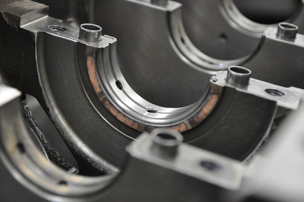 [7]
[7]
With all of the components cleaned and properly lubricated — place the crankshaft on top of your upper main bearings, set your main caps into position (verifying that each cap is back in the correct position and orientation), then lightly tap the cap into place until fully seated and tighten your freshly cleaned fasteners hand tight only.
To align the thrust bearing (which is used to limit end play), use a pry bar or rubber mallet to shift the crank back and forth, ending with it in its forward-most position; then, starting with the center main cap and working your way out from there, carefully begin torquing each cap fastener to the load specified by the manufacturer. If installed properly, the crankshaft should still rotate freely after each cap is torqued.
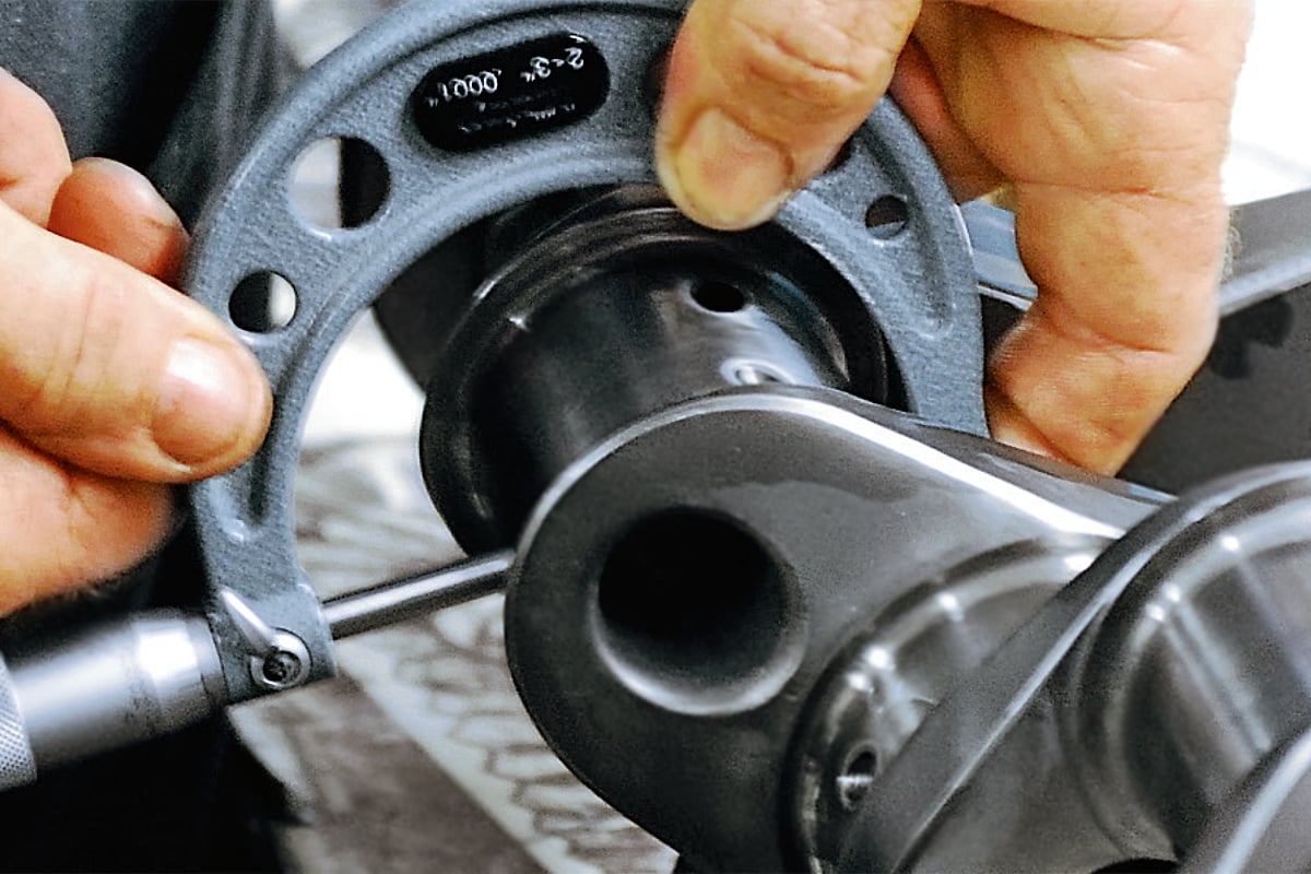
Prior to installing the connecting rods, verifying that the crankshaft’s end play (axial slack) is within tolerance is one of the final and most important steps in securing your rotating assembly.
Failure to verify end play can lead to a whole host of problems — too tight and not enough space will be left for the metals to expand as they heat up, leading to higher oil film temperatures, a complete lack of lubrication all together, or even binding of the crank itself; too loose and the crankshaft will literally bounce around, causing timing alignment issues and extreme wear on the bearings and crankshaft.
Again, with the crankshaft in its forward most position, set a dial indicator on the snout side of the crankshaft and zero it out. If you have an aluminum block, simply bolt a small steel plate somewhere within reach on the block for the dial indicator’s magnetic base to mount to. Then, using either a pry bar or rubber mallet, force the crankshaft in the other direction until it stops and then read the dial.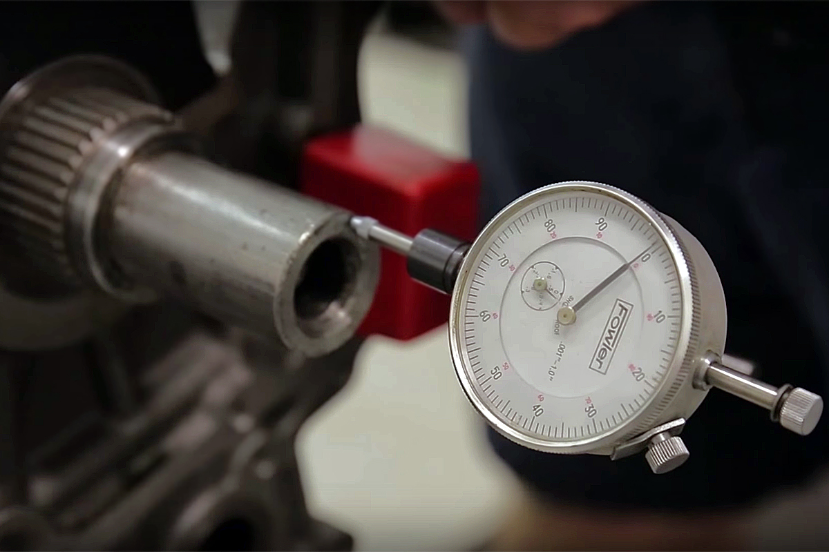 [8]
[8]
End play slack between 0.002 and 0.008-inch is generally preferred for most applications, but this value may be wider or tighter depending on the specifics of your build, the application, and how it will be ran. So be sure to verify your readings against the factory service manual or crankshaft manufacturer for reference.
For the full twelve-step guide, along with a number of other engine bearing related technical write ups, check out the complete tech repository [9] on King Engine Bearing’s website [10].