Way too many years ago, Bob Dylan wrote that, “The times, they are a-changin’” and that can be dramatically underscored with the changes that GM has made to the gasoline direct injection engines like the Gen V LT1 and truck engines. While direct injection (DI) is what has gathered all the attention around the LT1, the DI cylinder heads are also significantly different.
The flow numbers for these heads are amazing for a production cylinder head, but the aftermarket is famous for always wanting more. We stopped by West Coast Racing Cylinder Heads (WCRCH) in Van Nuys, California recently and owner Richard Reyman showed us his approach to CNC porting these heads. His process is very similar for upgrades to all of the most popular GM direct-injected engines. In addition to the LT1, that includes the 90-degree V6 4.3L (262ci) engine and of course the L83 5.3L (326ci) and the L86 6.2L (376ci) truck versions.
Reyman started this discussion by commenting that the LT1’s intake port is very large – over three square-inches at its largest cross-section. He says GM’s cylinder head designers have moved away from concern over port velocity because with direct injection inlet velocity is no longer crucial for maintaining fuel in suspension. The bullseye now is airflow. With previous engines, intake port velocity was crucial because if the air moved too slowly, the fuel (being heavier) could fall out of suspension. Direct injection eliminates those concerns.

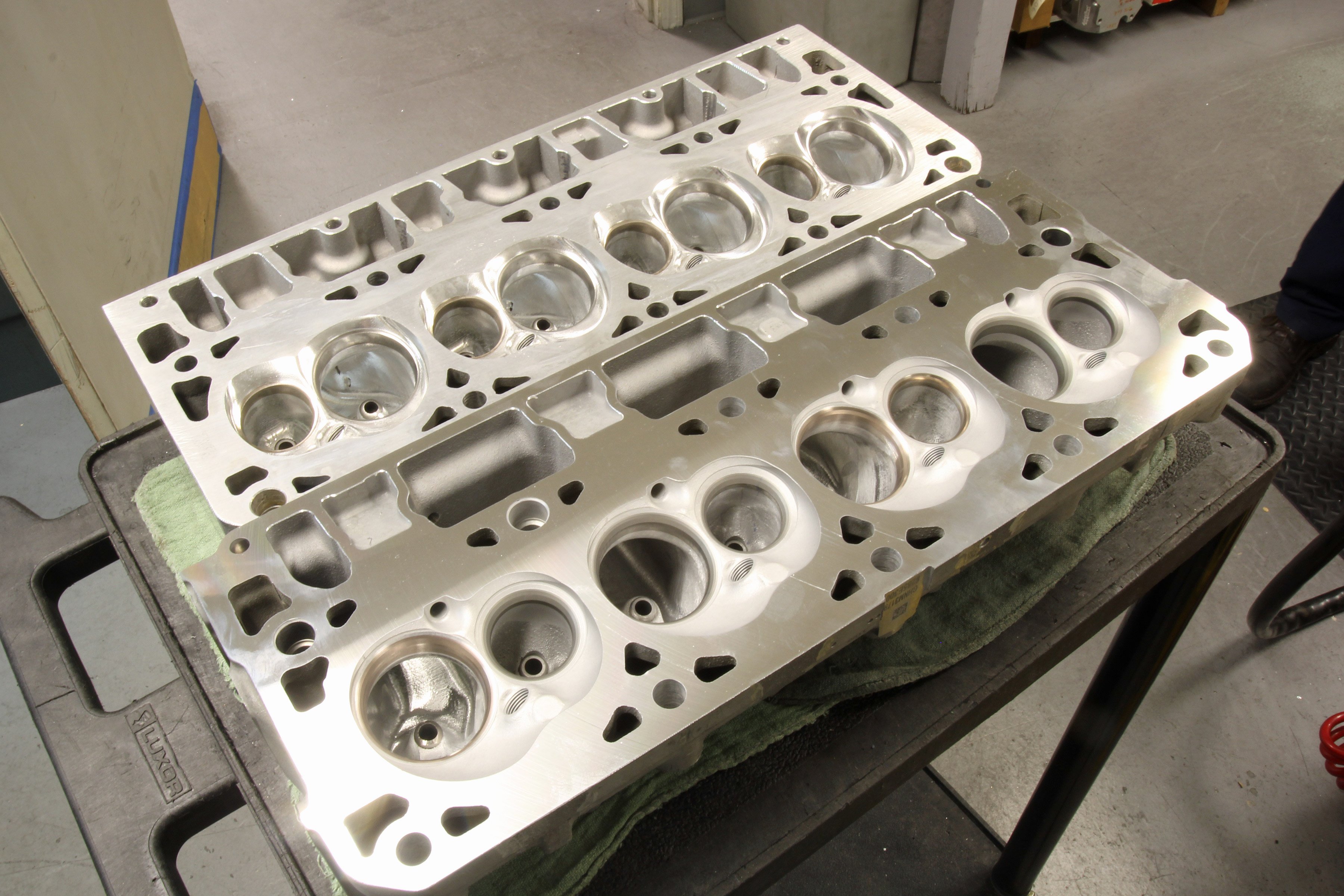
The 90-degree V6 head is on the bottom with a stock 5.3L head in the middle and the 6.2L LT1 head on top. The intake port entries for the V6 and 5.3L heads are the same but the LT1 head is taller by roughly 0.080-inch, making it 2.125-inches tall.
Sibling Similarities
We will focus mainly on the 5.3L and 6.2L V8 engines, but WCRCH is also working on port programs for the 4.3L V6 heads, as they are very similar to their 5.3L cousins. Reyman says the V6’s chamber layout is wider because the V6 engine features a bigger bore compared to the 5.3L. Ironically, with a slightly shorter intake port height, the V6 and 5.3L heads are generally very similar to the larger 6.2L V8 intake port.
An often overlooked area of importance is the valve angle. The direct injection engines – and specifically the LT1 – command an even taller valve angle than its predecessors. In addition to the extra angle, GM’s engineers have given the valves a tilt. Both the LT1 intake and exhaust valves now sport an 11.75-degree valve-angle whereas previous Gen III and majority of Gen IV engines had a 15-degree angle.
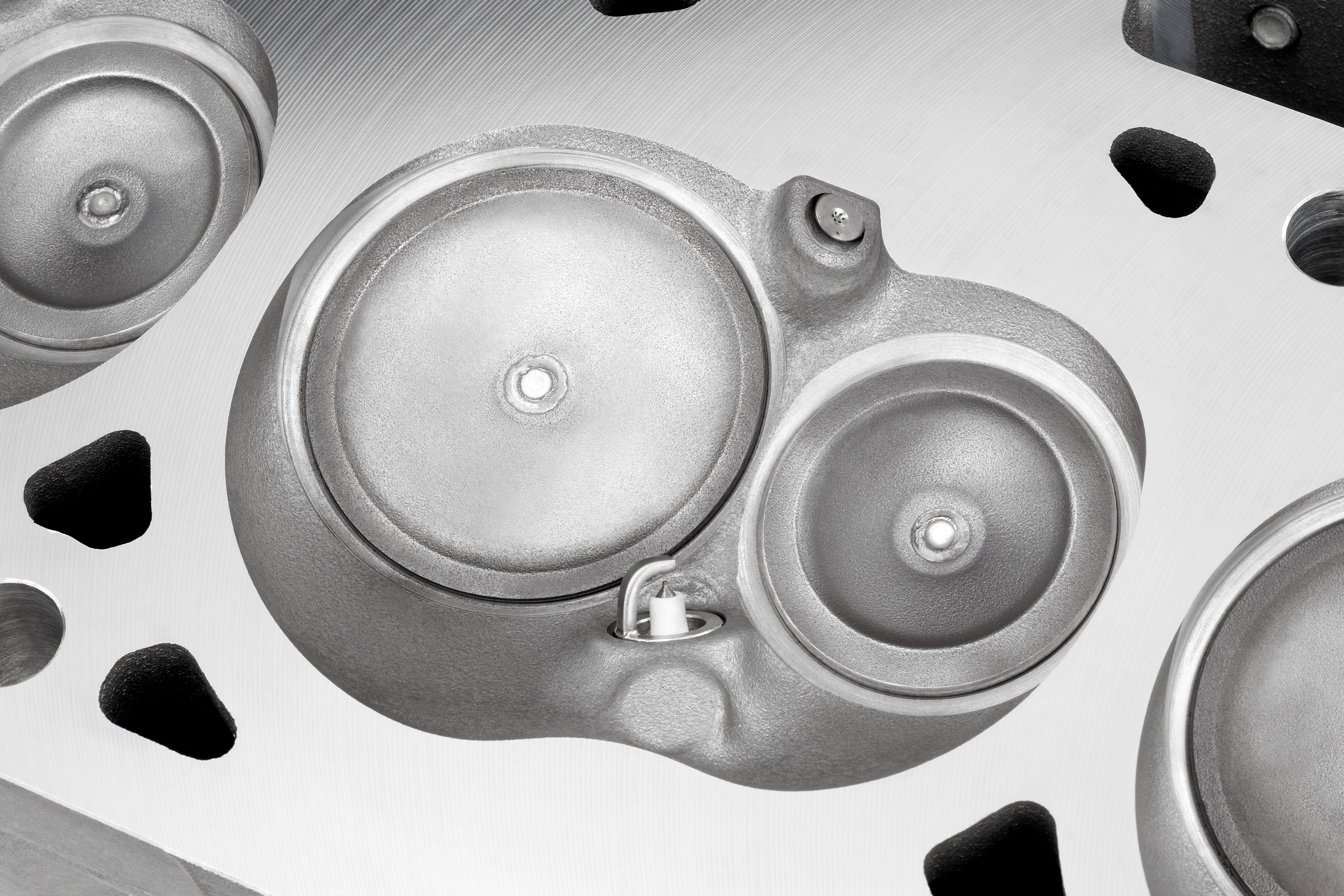
The direct-injection Gen V heads (left, bottom) are substantially different from their previous LS cousins (left, top). The most important difference is that GM switched the valve relationship. Both heads are symmetrical but note how the valves have traded locations in the chamber. On the right is a stock LT1 combustion chamber illustrating how the injector is located to direct fuel toward the center of the chamber. Also note how far the spark plug protrudes into the chamber which improves combustion efficiency with a centralized position.
However, the LT1 also cants the intake 3.75 degrees toward the center of the cylinder bore much like its ancestor, the big-block Chevy. The advantage to this incline is that flow is now aimed at the center of the cylinder bore as opposed to opening toward the cylinder wall. The Gen V exhaust valve angle isn’t as extreme as the intake, employing a gentler 1.50-degree cant.
This Is The Way We Flow
By now you’ve probably jumped right to the flow chart numbers so you already know that the stock intake ports in these heads measure 304 cfm before they nose over after 0.550-inch of valve lift. On the exhaust side, the stockers continue to climb all the way to 0.700-inch, moving 214cfm at 0.550-inch lift. With CFM, not necessarily port velocity the main goal, WCRCH has improved the exhaust numbers, flattening the curve out at 0.550-inch lift, bumping flow to 234 cfm, and pushing that even higher when the lift reaches 0.700-inch, to 252 cfm.
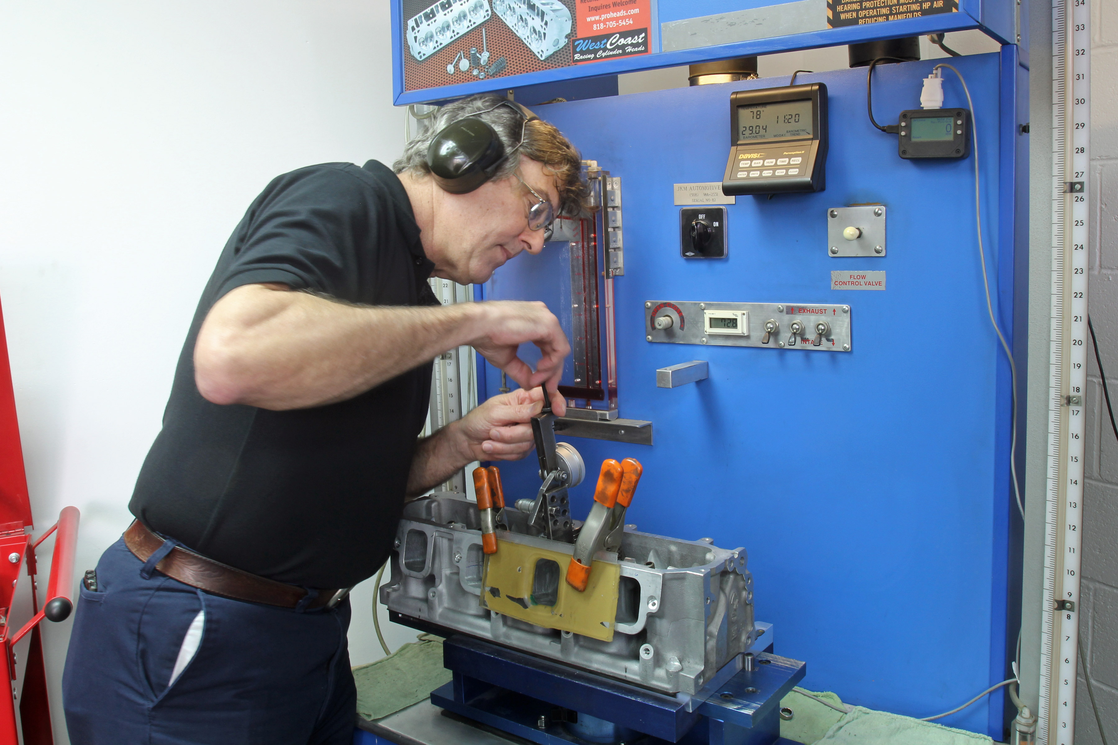
Richard Reyman’s flow numbers are all generated on his own flow bench. Because everybody’s bench is slightly different, it makes apple-to-apple comparisons with other flow claims difficult.
These flow numbers reveal that the factory is squeezing all they can out of ports from the start, making it increasingly difficult to create big gains in flow numbers. In the Gen I small-block Chevy days, a little work with a grinder could produce hefty improvements but the task of upgrading factory castings is now far more challenging.
The factory has already enlarged port size and volume, so really, there are no easy improvements to be gained, except for the bowl area around the valve. The flow bench curves are a direct reflection of what’s going on in the port, and Reyman says these large rectangle port heads offer over three square-inches of flow area.


(Left) All of WCRCH’s port work starts with digitizing the ports, which Reyman then uses to help create the CNC porting programs. The intake port is shown in red along with its relationship to the cylinder. (Right) Note how the stock Gen V exhaust port (shown here in blue) wraps around the intake as it exits the head instead of using a more direct path.
The restriction on any cylinder head is the bowl area followed by what is called the “flow curtain area.” The flow curtain is the area between the valve seat and the valve at a given valve lift. Huge production 2.120/1.59-inch valve sizes for the 6.2L engines means that the search for flow improvements will be limited to the bowl area within two inches of the valve seat. Valve diameter and lift are the two contributors to valve curtain area and make it easy to calculate.
First multiply the intake valve diameter times Pi (3.1416) to establish the valve circumference. For the LT1, this would be a valve diameter of 2.120 x 3.1416 = 6.66 inches. Then multiply that times valve lift to establish the flow curtain area. Using a valve lift of 0.500-inch we get 6.66 x 0.5 = 3.33 square inches. Using this formula, we can determine that valve lift would have to exceed 0.450-inch before the flow curtain area exceeds the three square-inch mark.
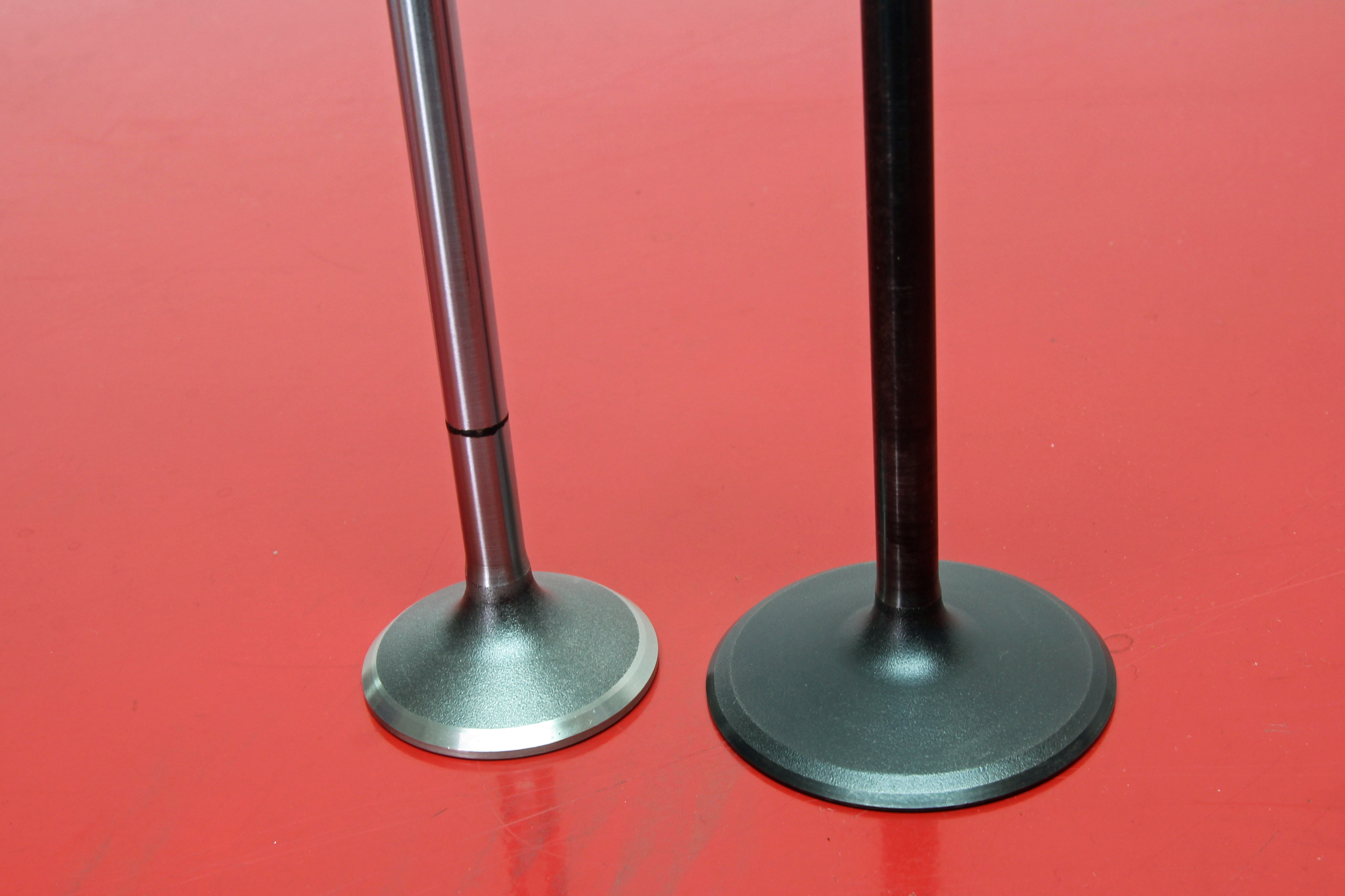
LT1 valves are 2.120 and 1.59 and the stock intake valve features a nice black nitride coating. WCRCH’ s Stage 2 porting offers a larger Manley 2.165-inch intake and a 1.600-inch exhaust.
Punching The Throat
However, there is an area called the “throat” located just below the valve seat, and the throat is the tightest area in the entire port. Not surprisingly, this is where most flow improvement work concentrates. Generally speaking for a performance engine, the throat diameter should not exceed 90-percent of the valve diameter. So with a valve diameter of 2.120-inches, the throat diameter should not exceed 1.91 inches. This becomes the smallest cross section in the port.
Opening the throat diameter beyond 90-percent has the effect of improving the high-lift flow but at the cost of reducing low- and mid-lift flow. This is not something that Reyman recommends or employs since the entire curve is important to optimum performance – especially for street engines.
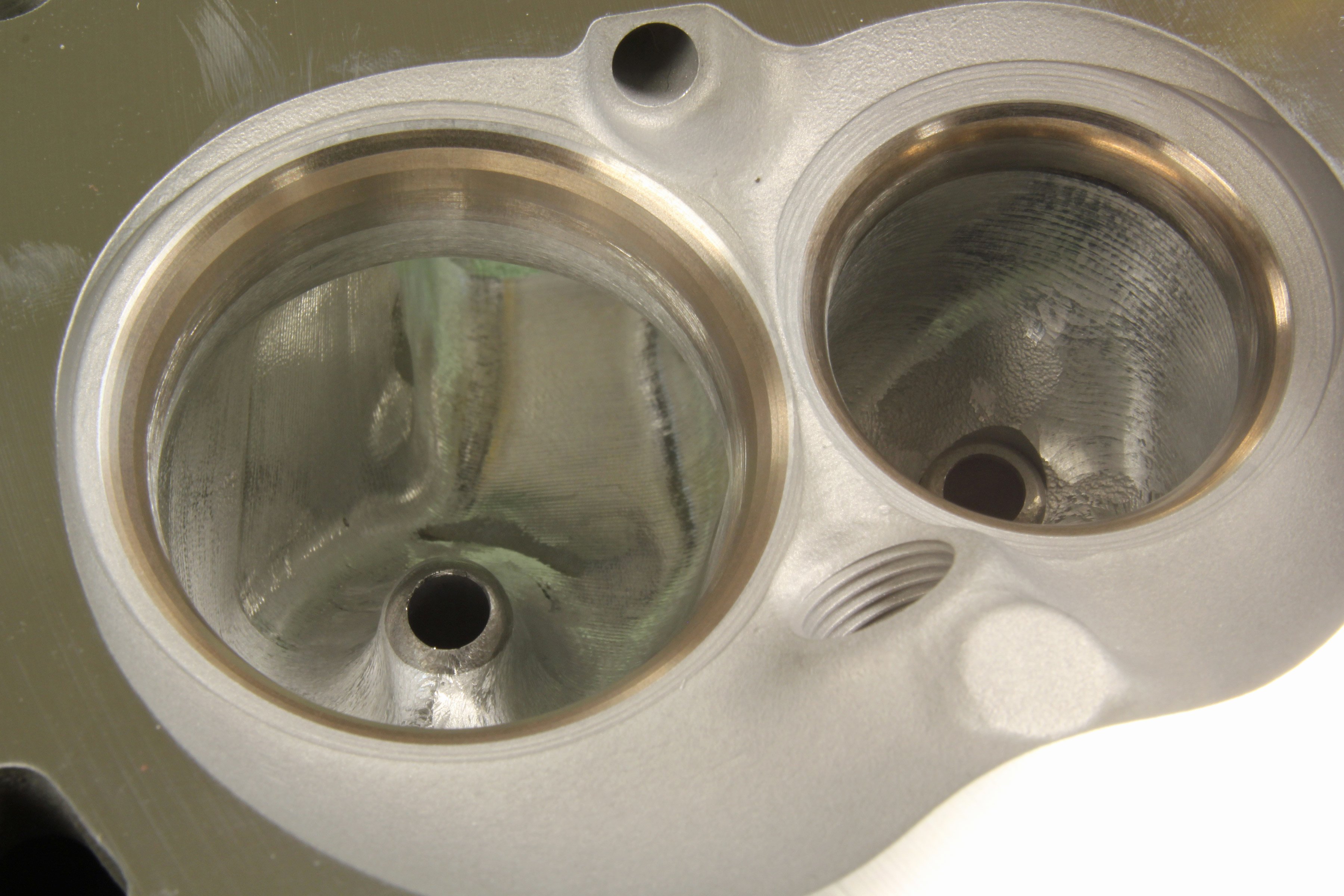
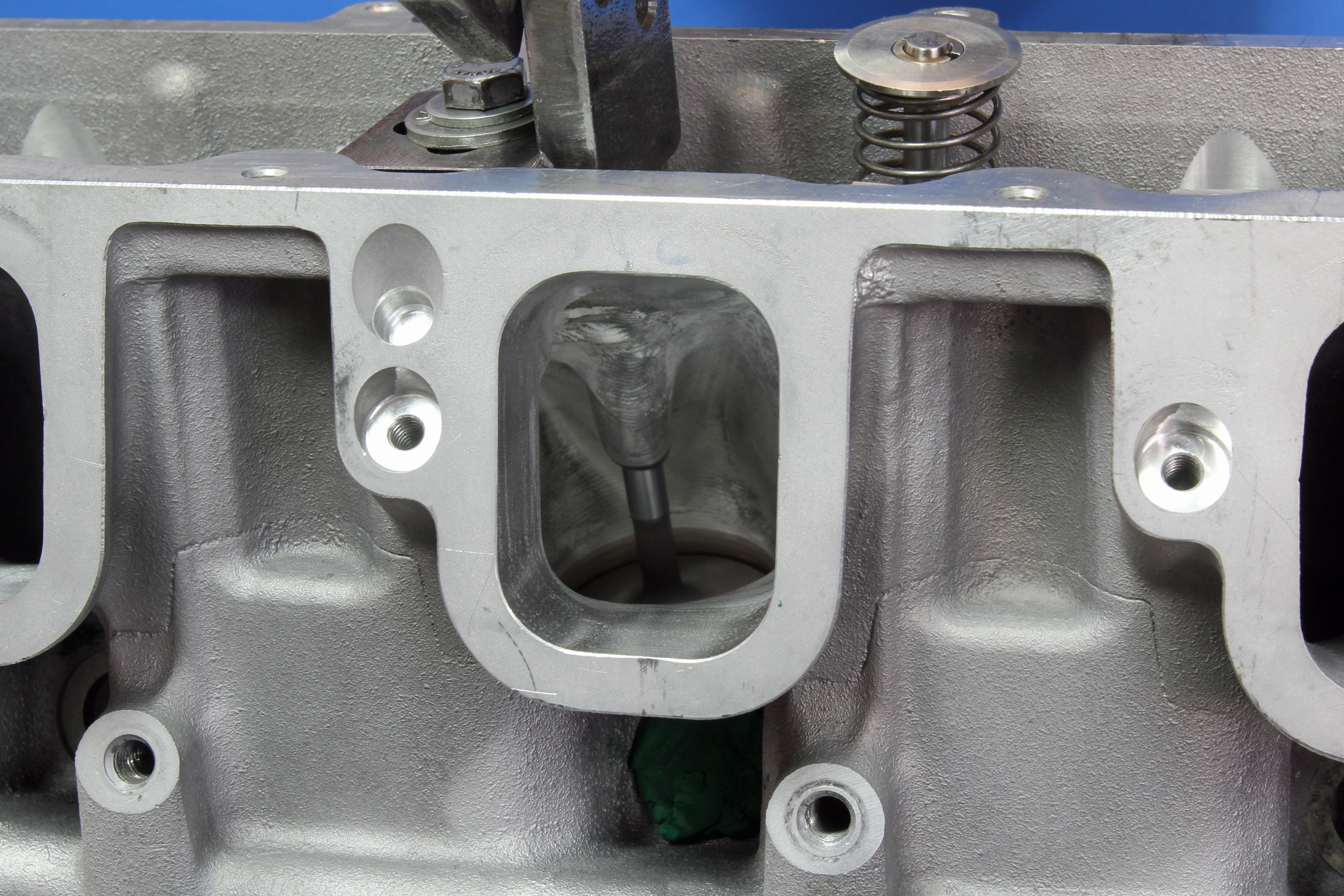
(Left) The majority of work on the V6 and V8 heads all concentrates in the bowl area. This is where all the improvements are gained in terms of moving air past the valve in the throat area. (Right) This is a blatantly generalized statement, but as exhaust port flow improves, it often means less exhaust cam timing is required and the greater flow also contributes to increased horsepower at high-RPM.
Reyman also told us that this is most definitely a work in progress and that additional efforts will likely improve upon these early numbers. But one look at flow numbers of 336 cfm at 0.600-inch lift and you know these are some impressive flowing heads.
These LT1 ports are equal to aftermarket rectangle port big-block flow numbers. We’ve come a long way from the old small-block Chevy days when a stock set of iron “fuelie” heads might struggle to achieve 220 cfm. WCRCH has now pushed a CNC-ported LT1 to almost exactly 50-percent more flow.
| Valve Lift | LT1 Intake, Stock | LT1 Intake, Ported | LT1 Exhaust, Stock | LT1 Exhaust, Ported | Ported Exhaust Flow vs. Ported Intake Flow* | |||
| 0.100 | 64 | 62 | 45 | 55 | 89% | |||
| 0.200 | 134 | 132 | 120 | 113 | 85% | |||
| 0.300 | 207 | 207 | 151 | 162 | 78% | |||
| 0.400 | 258 | 264 | 184 | 204 | 77% | |||
| 0.500 | 295 | 307 | 210 | 232 | 75% | |||
| 0.550 | 304 | 321 | 214 | 247 | 77% | |||
| 0.600 | 290 | 336 | 223 | 249 | 74% | |||
| 0.700 | 295 | 326 | 228 | 252 | 77% | |||
| 0.750 | — | 333 | 234 | 251 | 75% |
*Exhaust-to-Intake ratio is a way to express the overall flow efficiency of a cylinder head. The ideal percentage varies from expert to expert, but being in the 72-80-percent range is often considered ideal.

All tests performed at 28 inches of water test depression on a 4.065-inch bore.