

The intake manifold is one of the most influential components in any performance engine build, yet it remains one of the most misunderstood. On GM’s LS and LT platforms, which power everything from daily-driven Camaros and Corvettes to purpose-built race machines, manifold selection and design can mean the difference between a flat, uninspiring power curve and one that delivers exactly what the application demands.
This article explores the engineering principles behind LS and LT intake manifold design: how plenum volume, runner length and diameter, port velocity, and resonance tuning all interact to shape an engine’s performance character. We will also look at how advanced manufacturers like Performance Design leverage materials, CNC machining, and precision engineering to push these principles further, and examine how modern systems like the Intake Manifold Tuning Valves found in the C8 Corvette Z06’s LT6 engine have changed the game.
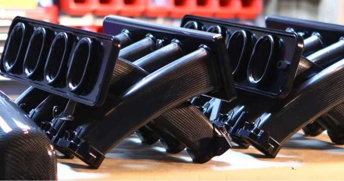
The Lungs Of The Engine: Plenums And Runners
Think of an intake manifold’s plenum and runners as the lungs and bronchial passages of your engine. The plenum acts as the central air reservoir — the chamber where incoming air accumulates before being distributed to the runners, the individual passages that carry air from the plenum to each cylinder head port. The geometry of both has a profound impact on where and how power is made.
Plenum Volume: Air Reservoir And Throttle Feel
The plenum sits between the throttle body and the individual intake runners. Its volume determines how much air is immediately available at any given moment, with significant consequences for throttle response and power character.
A larger plenum primarily functions as a flow-management tool rather than simply as an air reserve. The increased volume slows incoming air from the throttle body, promoting more even flow attachment across the plenum and increasing the probability of adequate air delivery at each runner entrance. Slowing the air also raises manifold absolute pressure, benefiting cylinder fill. More plenum volume nearly always improves ultimate power output. While the old concern was that too much plenum volume hurt throttle response, modern LS/LT engines move air so efficiently that this is rarely a practical concern at volumes achievable in real-world packaging.
A smaller plenum maintains higher air velocities and lower manifold absolute pressure, delivering sharp, immediate throttle response. The trade-off is that at elevated engine speeds, a small plenum can become a bottleneck: unable to sustain adequate supply to all runners under peak demand, limiting top-end power. The ideal plenum size is a function of engine displacement, target RPM range, and intended use. A street-driven LS3 and a purpose-built LS7 road-race engine have fundamentally different requirements.
It is also worth noting that plenum flow is inherently chaotic. The firing order creates a constantly shifting windstorm inside the plenum as pressure pulses from each cylinder’s intake event interact and overlap. As Performance Design owner Caleb Newman puts it: “Plenums don’t matter unless you screw them up.” That said, features like the proximity of plenum walls to bell mouth runner entries, or tangential flow paths parallel to runner entrances, can substantially alter the effective tuned length of a runner — for better or worse depending on the application.
Runner Length, Diameter, And Acoustic Resonance
Runners direct air from the plenum into each cylinder’s intake port. Their length and cross-sectional area determine both airflow velocity and acoustic resonance characteristics: the mechanism that governs where peak torque and horsepower are achieved.
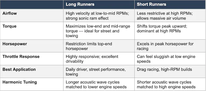
Understanding why runner length matters requires a look at one of the most powerful and often overlooked forces in engine breathing: acoustic resonance, specifically the Helmholtz Resonance effect. When the intake valve opens, a negative pressure wave travels back up the runner toward the plenum. When it reaches the plenum, it reflects back as a positive pressure wave. If the runner length is tuned correctly, this positive wave arrives back at the intake valve just before it closes — effectively ramming additional air into the cylinder beyond what atmospheric pressure alone would deliver. This phenomenon is called resonance supercharging or ram tuning.
Because pressure waves travel at approximately 1,100 feet per second in intake-temperature air, the timing of the return wave is a direct function of runner length. Longer runners create a longer travel path, meaning the resonance effect peaks at lower engine speeds, aligning with a low-RPM torque peak. Shorter runners produce a faster wave cycle, tuning resonance to higher engine speeds. The runner is not just a conduit, it is a tuned acoustic instrument. “Runner length is everything when it comes to where you make power. If you get the tuning right, the engine is essentially supercharging itself through resonance. Get it wrong and you’re leaving significant power on the table across the entire RPM range” explained Newman.
Port Velocity And Volumetric Efficiency
A common misconception is that larger intake ports always equate to more power. In reality, port velocity — the speed at which air travels through the port — plays an equally critical role. Slow-moving air carries less kinetic energy into the cylinder, reducing the ram-charging effect at low and mid engine speeds.
A compelling example is the Gen V LS6 engine. Despite featuring a large plenum and short runners designed for high-RPM output, the LS6 uses a comparatively narrow intake port. This deliberate design choice increases port velocity, creating a supercharger-like ram effect as air accelerates into the combustion chamber, resulting in an engine that maintains strong mid-range response while still achieving impressive peak numbers. Smaller ports, when properly matched to engine displacement and RPM range, can dramatically improve cylinder fill efficiency at mid-range engine speeds.
In practice, manifold designers rarely have free rein over absolute port cross-section since the port opening is typically dictated by the cylinder head being matched. Development focus therefore shifts to runner taper, or the rate at which the runner cross-section changes from plenum entrance to head port. The LS3, for example, responds poorly to aggressive taper or short runners, while other LS and LT heads show more tolerance for, or even benefit from, varying taper and length combinations. Taper also interacts with resonance tuning, effectively altering the runner’s acoustic behavior and shifting the RPM at which peak resonance charging occurs.
Volumetric efficiency (VE) is the percentage of air a cylinder actually ingests compared to its theoretical maximum capacity. Through resonance charging and careful induction design, it is possible, and common in high-performance applications, to exceed 100% VE, where the momentum of incoming air and acoustic pressure waves force more air into the cylinder than its static volume would suggest. Torque peaks directly correspond to the RPM range where VE reaches its maximum, which is why manifold selection is inseparable from camshaft selection, exhaust design, and cylinder head porting.
Performance Design: Engineering At The Leading Edge
While factory GM intake manifolds represent impressive engineering within cost and packaging constraints, the performance aftermarket has pushed manifold design significantly further. Performance Design, led by owner Caleb Newman, has earned a strong reputation in the LS and LT community for producing intake manifolds that combine rigorous aerodynamic principles with precision manufacturing.
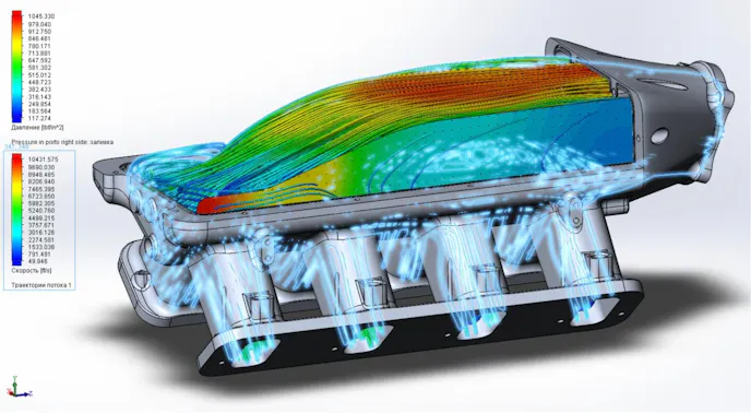
Performance Design’s approach centers on first-principles fluid dynamics — analyzing airflow behavior through each stage of the induction path, from throttle body entry through plenum distribution and into individual runners. Rather than simply scaling existing designs or copying factory geometry, Performance Design manifolds are developed through computational fluid dynamics (CFD) modeling and real-world dyno validation. CFD simulation maps pressure distribution and airflow velocity across all runners, revealing exactly how air distributes cylinder-to-cylinder. As Newman explains: “Every manifold we design starts with airflow data. We model how air behaves as it transitions from the throttle body into the plenum, and we pay close attention to distribution, making sure all eight cylinders see as close to identical airflow as possible. An uneven manifold might look great on a dyno number, but three cylinders are working harder than the rest, and that costs you reliability and consistency.”
Manufacturing Methods
CNC Machined Billet Aluminum provides speed and flexibility: it enables low-volume product variants with minimal tooling investment, making it ideal for developing new designs and serving niche applications. The geometry achievable with billet machining rivals or exceeds casting for complex internal passages. Notably, a mirror-polished surface is counterproductive in airflow applications, as it promotes laminar boundary-layer friction; a quality machined finish sits at the upper end of the ideal roughness range. The primary downsides are weight and heat soak. Aluminum absorbs and radiates heat to the fresh air charge, which can reduce charge density in high-output applications.
High-Quality Plastic Composite Molding, specifically glass-filled nylon, represents the best overall balance of performance, weight, and cost, serving as the workhorse of both OEM and aftermarket manifold production. Polymer manifolds can achieve burst strengths of 9 to 10 bar or higher, well in excess of service demands. The thermal advantage over aluminum is significant: plastic absorbs and radiates far less heat to the intake charge, a difference that becomes dramatic in forced-induction applications where charge temperature is critical. Performance Design also employs a proprietary in-house nylon casting process that reduces tooling cost compared to injection molding while offering unique geometric capabilities, making it well-suited for lower-volume aftermarket performance applications.
Carbon Fiber Construction is selected when specific strength is the primary driver, delivering the lightest, strongest solution available while providing very low heat soak. Compared to billet aluminum, carbon fiber offers a superior strength-to-weight ratio, lower thermal impact on the charge, and often a cost advantage at comparable volumes. Performance Design’s carbon fiber manifolds for the GM LT2 in the C8 platform combine structural rigidity with significant weight savings in the woven carbon plenum lid, while the precision-matched runner lower delivers consistent cylinder-to-cylinder airflow distribution.
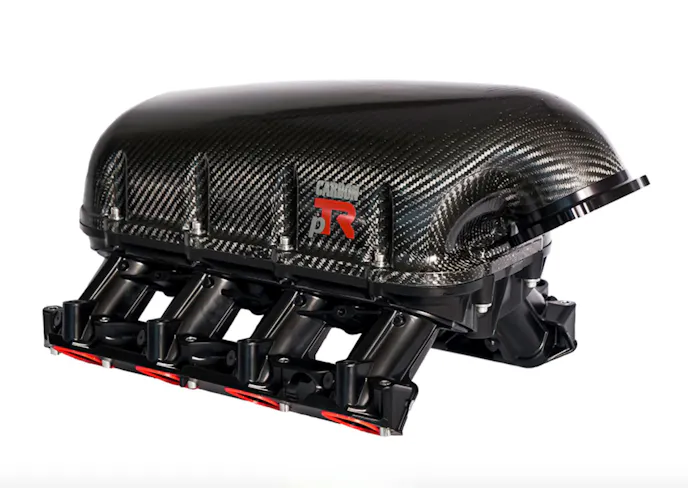
Beyond the engineering case, many enthusiasts upgrade their intake manifold as much for visual impact as for performance, and Performance Design’s carbon fiber pieces address both. “The material matters, but the geometry matters more. A beautifully machined manifold with poor internal airflow design will lose to a well-designed composite piece every time. We focus on getting the aerodynamics and tuning right first, then select the manufacturing method and materials that best suit the application.” Newman explained.
One area where Performance Design has invested significant development is the transition between the throttle body and plenum, where many manifold designs compromise. Sharp transitions, abrupt area changes, and poorly designed dividers can create turbulence that disrupts even distribution across runners. Performance Design incorporates carefully radiused plenum entries and optimized plenum geometry to promote laminar flow and equal cylinder-to-cylinder fill. As Newman explains: “The only thing we care about in CFD is getting air to the runner. Then the runner shape and length take over. But getting air to where flow in the runner develops is critical.” A smooth, well-contoured deceleration zone allows air to slow in a controlled manner, increasing density and allowing more uniform distribution to each runner entrance.
Variable Intake Manifolds And The LT6 Communicator Valve System
The ultimate engineering solution to the short-runner vs. long-runner trade-off is not to choose one but to use both, dynamically. Intake Manifold Tuning Valves (IMTV), referred to by GM engineers as communicator valves in the LT6 context, allow an engine’s induction system to physically reconfigure itself based on real-time operating conditions. Variable intake manifolds use electronically controlled valves to alter the effective length of intake runners, the volume of the plenum, or both, depending on engine speed and load. The penalty is complexity. But the reward is a broad, usable power band impossible to achieve with a fixed-geometry design.
The 5.5-liter LT6 powering the C8 Corvette Z06 represents one of the most sophisticated naturally aspirated variable induction systems ever fitted to a production automobile. As a flat-plane crank engine with an 8,600 RPM redline, the LT6 faces a specific challenge: delivering meaningful torque at everyday road speeds while unleashing exceptional high-RPM power on demand.
GM’s solution was a dual-plenum, dual-throttle-body intake manifold unlike anything previously produced for a street Corvette. Two molded-nylon chambers, each with an internal volume of 5.5 liters, are fed by dedicated 87 mm throttle bodies. The extensively ribbed, mirror-image plenums are joined along their lengths by three communicator valves — electronically controlled passages that selectively connect the two chambers. Inside each plenum, four molded-plastic trumpets channel air into the runners below, and each intake runner splits into two paths to feed a pair of titanium intake valves per cylinder.
The communicator valves are sequenced by the ECM with precision to optimize the Helmholtz Resonance effect at each stage of the rev range. Two of the three communicators operate in tandem as a paired set, while the third runs on an independent schedule, giving the ECM fine-grained control over plenum connectivity and resonance tuning at each RPM threshold.
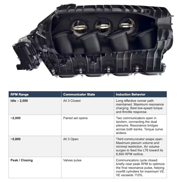
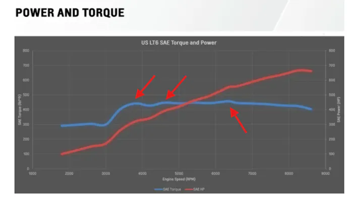
The result is an output curve unlike anything seen in a naturally aspirated production engine before the LT6. Rather than a typical arched torque curve with a single peak and rapid fall-off, the LT6 produces what GM describes as a nearly flat torque line, or actually a series of three short-duration humps blended by the communicator system, that culminates in a peak of 460 lb./ft. at 6,300 RPM. The communicator valve strategy allows the LT6 to effectively tune its own induction resonance on the fly, functioning as a continuously variable long-runner/short-runner system without a single moving mechanical component inside the runners themselves. The measured result is peak volumetric efficiency exceeding 110% and 670 horsepower from a naturally aspirated engine with genuine road-going drivability.
Choosing The Right Manifold For Your Build
With a thorough understanding of the principles at work, manifold selection becomes a systematic exercise rather than a guessing game.
Street-driven builds benefit most from longer-runner designs that maximize mid-range torque and drivability. Longer runners typically develop their resonance peak in the 6,000 to 7,000 RPM range, making them well-suited to engines that spend most of their time below that threshold, delivering the torque character and throttle response ideal for street use.
Track-focused builds designed to operate consistently above 7,000 RPM are candidates for shorter, larger-diameter runners and larger plenums that prioritize peak airflow volume. Very short runners, increasingly common in the aftermarket, target a resonance sweet spot around 10,000 RPM and require the engine to genuinely operate in that range to deliver their intended benefit. Unless the combination of heads, cam, and exhaust can sustain power at those speeds, very short runners offer little practical advantage for most builds.
Dual-purpose builds, or street cars that see occasional track use, are the strongest candidates for variable-geometry or IMTV-style solutions.
Intake manifold design for the LS and LT family involves a sophisticated interplay of plenum volume, runner geometry, port velocity, resonance tuning, and throttle body design, with each variable influencing where and how power is made across the RPM range.
From the Helmholtz Resonance effect that allows a well-tuned long-runner manifold to outperform its atmospheric limitations, to the engineering marvel of the LT6’s dual-plenum communicator valve system that delivers the best of both worlds in a production sports car, the principles at work are consistent: air mass, velocity, and timing determine torque, and the manifold is the primary instrument through which these variables are controlled.
Manufacturers like Performance Design demonstrate that the production manifold is rarely the endpoint, and that careful engineering, precision manufacturing, and a commitment to first-principles airflow analysis can unlock significant additional performance. For the LS and LT enthusiast, understanding these principles is the first step toward selecting or commissioning the right induction solution for their build.
You might also like
Win A 2026 3LZ Coupe Through The Corvette ZR1 NCM Sweepstakes Draw
The National Corvette Museum launched the Corvette ZR1 NCM Sweepstakes. One winner takes home a 1,064-horsepower mid-engine sports car.