In 2014 Gasoline Direct Injection (GDI) V8 power controls hit the scene, and what confusion there was! Now enter 2019, the concept of GDI has taken on a household name yet many still look upon it as a mystery. Follow along as we try and debunk all the internet buzz and spotlight some of the tools needed today to get it under control.
You must first remember that the internal combustion engine has remained virtually the same since its inception, which is well over 100 years ago, and for this, the basics still apply today. We all at this point should recognize that the engine is an air pump. The downward stroke within the cylinder creates a low pressure which then draws high-pressure air from the atmosphere. Throwing some fuel into the mix, compressing it and lighting it off creates the energy needed to produce power.
By the laws of physics; airflow and torque have a direct correlation. Why is this important? It’s because it’s the basis of today’s torque-based engine management control systems.
Since the beginning of General Motors hard entry into fuel injected engines — let’s say in 1997 when the LS motor was released — they have used two distinct methods to measure this airflow into the engine. These would be noted as Mass Air Flow (MAF)-based which is direct-measured, and Speed Density-based which is calculated. The logic behind the use of two air models is that the Speed Density mode is better for transient changes and the Mass Air method is more accurate during steady state conditions. Transient is when there are quick changes to throttle/load whereas the MAF works very well during linear airflow. Since both of the conditions are continually varying, it’s crucial that both models agree. The factory has spent countless hours to define these functions which have made today’s cars pretty seamless to drive. However, when you decide to modify your engine, all goes haywire!
Mass Air Flow Model
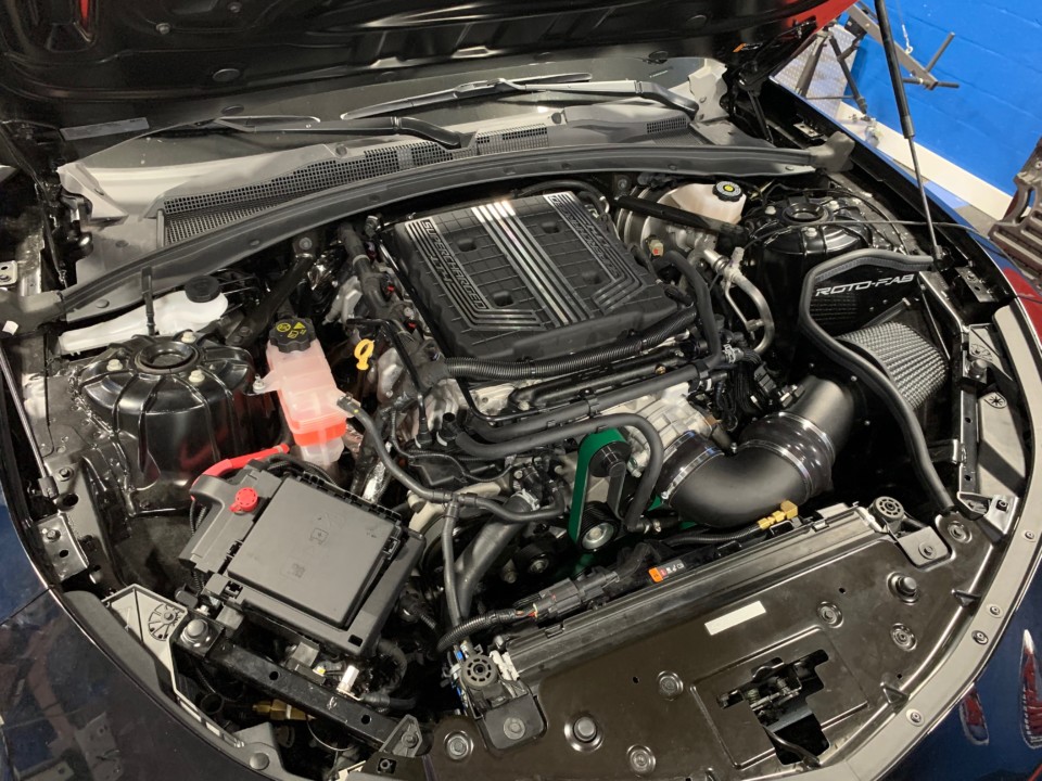
The Mass Air Flow Sensor is the first sensor in the chain of ingesting air. Any changes made to the inlet tract from the factory will require a correction to the MAF curves in the car’s ECU. An excellent example of this could be the use of a large 5-inch aftermarket cold air intake or the 4-inch new inlet pipe on your centrifugal supercharger.
As airflow travels past the MAF sensor, it converts a measurement of hertz to grams/second values. The ECU uses these values to calculate fueling, also in grams/seconds, so the correct proportion of air and fuel are mixed which is essential for engine performance. In the early years of MAF based systems, this was all the MAF needed to do. Today’s new controllers take this another step further by using that grams/second value and converting it to a torque value in Newton Meters. Hold this thought as we will come back to it.
Speed Density Model
The Speed Density model is a bit more complicated as time has evolved. SD has been around in aftermarket controllers for years and looks at manifold pressure, engine RPM, and temperature, then references to a “look up” value. This form of air modeling is much more specific as the values need to be correct and remain as they are vs. MAF which can vary with mass over time. In 2006 GM took this to a whole other level using a complex seven string polynomial calculations to determine this value, yeah big words and for a good reason. Today’s modern engines are not as two dimensional anymore as they once were. With variable valve timing, variable manifold runners, flex fuel and various forms of factory forced induction; today’s engines can vary their volumetric efficiency on the fly based on demand. If this were done through a two-dimensional table, there would need to be thousands of them in a controller that would most likely need to take up the entire trunk. This is where the polynomial calculation comes into play. Like any equation, there is input data which eventually solves something. In this case, the calculation looks at RPM, Manifold Absolute Pressure (MAP), temperature, spark, and camshaft degrees.
Unfortunately, the tools needed to extrapolate these values accurately is above most enthusiasts’ pay grade. However, the aftermarket has created some tools to get us closer to the resolve.
What’s important is that both models, as different as they are, must report the same air mass for the system to work correctly. The process to do this properly is best left for another writing as it gets quite involved.
Torque Based Control
Today’s controllers (such as the LT1’s E92) now use torque as its primary target of control. Again this is natively expressed in Newton Meters (NM) of torque. We can take a look at idle as a simple example. Anyone who has ever assembled an engine has manually spun the engine over on an engine stand and felt the resistance and drag of all the moving parts. If you take a torque wrench, you can approximate how much torque is needed to rotate it. For an engine to idle you need to produce more torque, then the value of resistance or the engine will not idle. Going back to the rule of torque and airflow go hand and hand, as you can see we need to move more air to make added torque to overcome the friction. Not enough air and it won’t idle. Too much air and it will idle high.
When you decide to turn on the AC, you add more load to the engine and therefore need more torque. Then the ECU commands the electronic throttle body to crack the blade and provide this air and make more torque. While this is an example of adding torque, much of the torque based control system is utilized to take torque away.
The transmission, traction control, and torque management all function by removing torque.
The transmission determines its shift patterns and characteristics based on torque. This information is transmitted from the engine controller to the transmission controller, which is why the engine calibration must be on point. You can’t put 480 nm of torque through a transmission that is expecting 300 nm. If this is the case, significant wear or damage to the transmission is expected.
Everyone seems to throw the words “torque management” around as if it’s the plague of the car. This is far from the truth. Torque management is exactly as it states, a logic to manage the torque. Well, you might say: who cares? The OEM utilizes this strategy so they can keep the vehicle from breaking under adverse conditions and provide a warranty. If the rear axle can only handle 4,500 nm of axle torque and the engine is now capable of producing 5,000 nm; the controller can request a torque reduction via pulling the throttle and reducing spark timing. This same logic also applies to the transmission as well as traction control. You can now start to see why things are torque based.
Now let’s look at what happens when we start to increase the output of an engine. Let’s say we take a 2018 ZL1 powered with the LT4 supercharged engine and jamb in a bigger camshaft while swapping the stock 1.7-liter supercharger for a Whipple 2.9L, and include all the other trimmings, before strapping it onto the rollers. At this point, it’s safe to say that all these changes were not what the original calibrator had in mind. That mammoth 5-inch cold air intake is sure to skew the stock MAF transfer function, and there is no doubt the larger camshaft has moved the engines volumetric efficiency to the north of its stock location. For the engine to perform correctly, these will have to be fixed to ensure fueling is correct and subsequently the final torque values that are derived from the airflow.
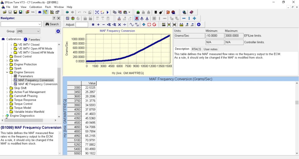
Focusing on the MAF transfer function, first we need to reestablish a new curve that provides the controller the correct airflow to Hertz. Here is the table for the MAF that needs to be addressed.
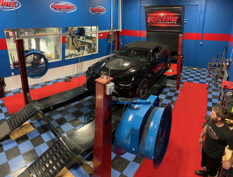
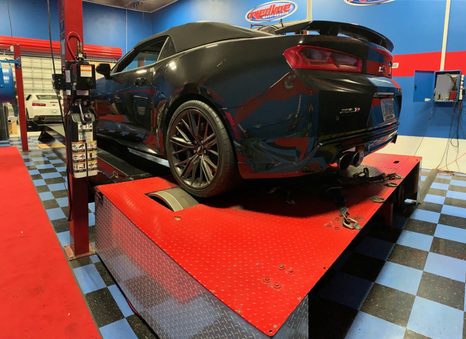
To solve this problem, we would need to force the controller into open loop as we do not want any contribution for correction to come from the oxygen sensors. It’s also essential to ensure we are commanding a lambda of 1, for this case that will equate to 14.2:1 air-fuel ratio, which is stoich for today’s pump gas with up to 10% ethanol. Using a load control chassis dyno, we can then hold the vehicle at the load breakpoints as defined in the MAF curve. If you note that you commanded lambda and lambda is off, you need to correct the error at that specific hertz break point. Once this has been performed for all cells, the new curves values will represent the actual airflow.
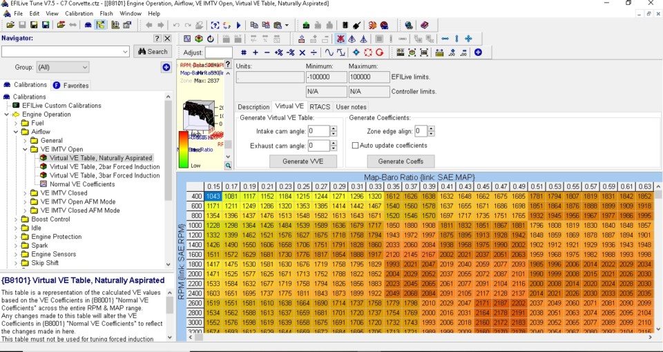
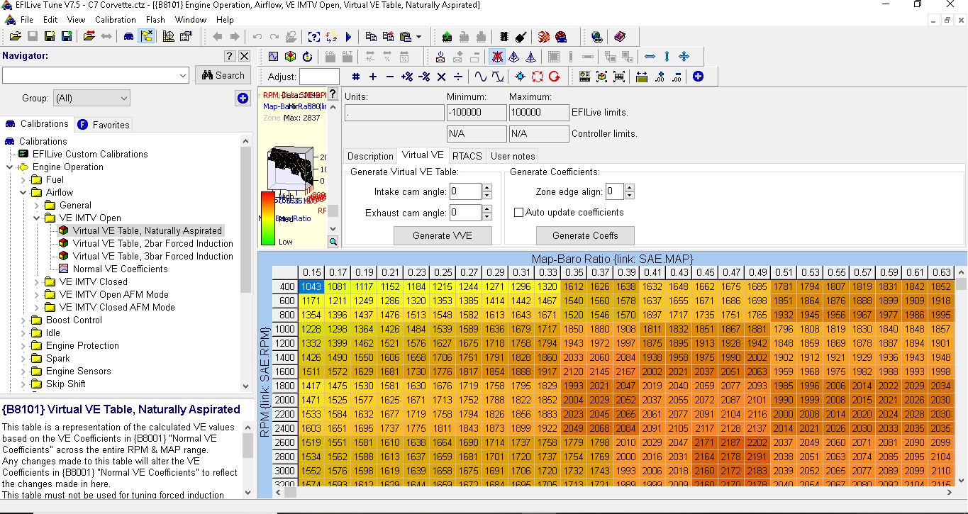
Now we need to address Speed Density, which is a bit more tedious. However, thanks to some neat tools within the EFI Live software this process has become much easier. Since the old style 2-dimensional volumetric efficiency surface table no longer exists, EFI Live has built a tool that allows the user to work off a “virtual” table that is represented like a 2D table but calculates the engineering coefficients that the modern controller uses for its fuel calculations. The following shows this table.
Again using a load controlled dyno, you can sweep through the different cells until as many are filled with the correct values. Once they are correct, the speed density model will represent the correct airflow at those loads in which these values can be converted to torque.
One of the first tables in the chain of torque controlled system is the Driver Demand table. This table represents driver input, via the accelerator pedal, which is then converted to a torque request. Depending on whether the vehicle is a manual or automatic transmission, the values in this table will either be kilowatts or axle torque respectfully. The torque request is then sent to the part of the controller that handles the electronic throttle control. This request is made through a calculation called the compressible gas formula. In layman’s terms, it determines a target manifold pressure which is determined by the throttle blade opening. High-pressure air enters the manifold changing this pressure, which is how most drive-by-wire cars connect the pedal to the blade.
Now the fun begins!
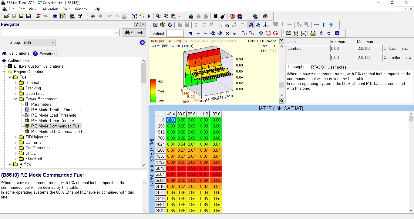
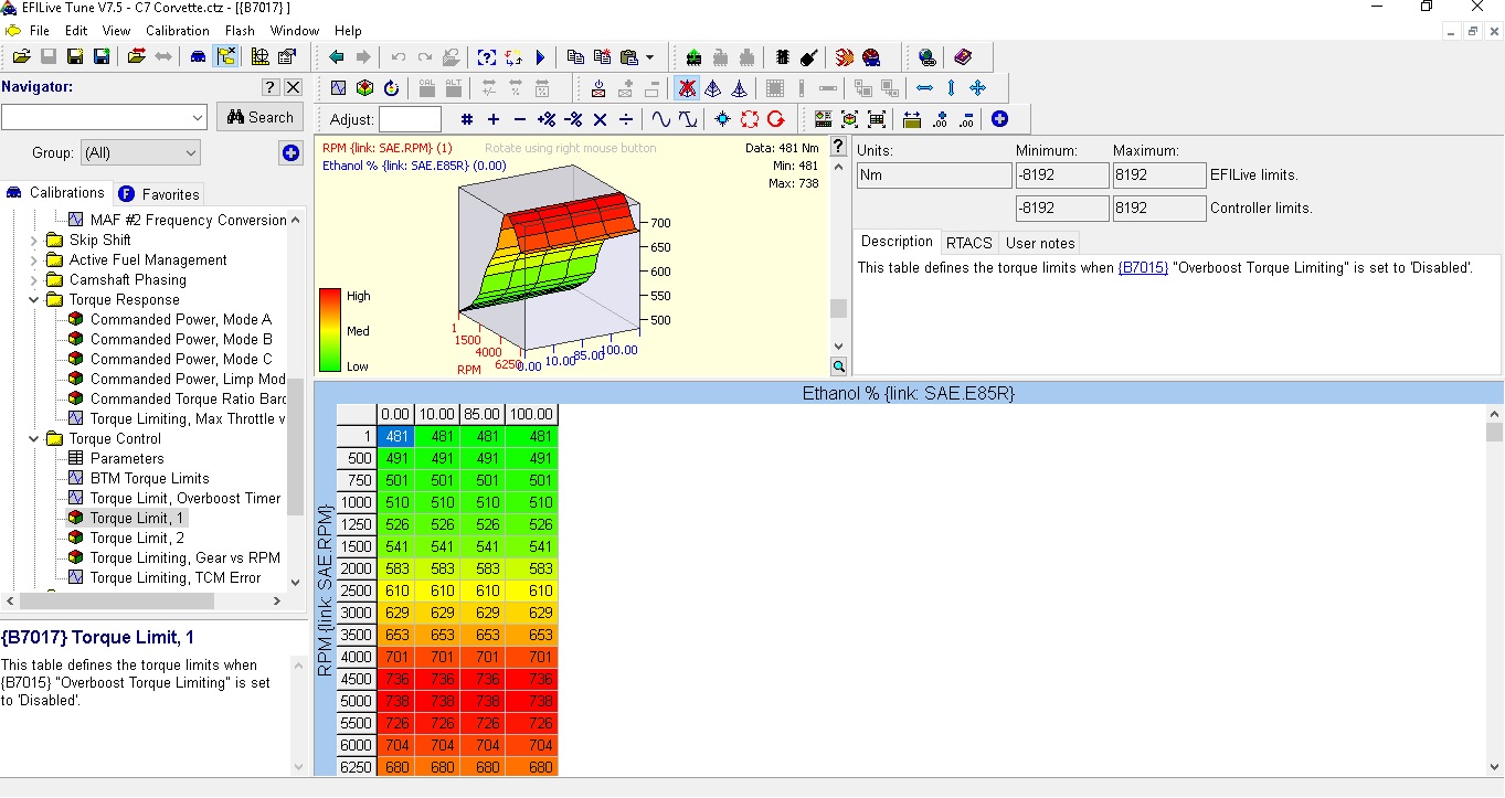
Before the blade can open to its final angle, more decisions must be made within the controller’s logic. Throughout the controller are numerous tables that are limited to how much power can be made. From the factory, these tables are typically just above the engine’s max power output and don’t typically hold back a lot in max power. However, the installation of high-performance parts will most likely move power into these limits. For this, the tables need to be modified. Below are a few tables that can limit you reaching your goals.
Now that we hopefully have moved these limiters out of the way, we need to contend with other controllers that are waiting to see what the new torque output of the engine is. These being controllers like traction control, transmissions, and drivetrain part protection.
Traction Control Intervention
So you pull out on the avenue after all your upgrades and stab the pedal to the floor. The dash lights up like a Christmas tree, and the car feels very underwhelming. The traction control system is in the chain that connects your big right foot to the throttle blade. With numerous sensors ratting you out that the rear wheels are spinning 200-percent more than the front, the throttle is at 90-percent, and the brake system reports pressure on the pedal. The engine controller removes torque which is done through both throttle closures and spark retard as both of these take power away.
Transmission Control
Today’s transmission is quite a marvel of engineering. So much is going on inside the transmission that for it to work correctly, specific strategies have been employed to control all of this. I have often used the example of a relay race as a way to explain how an automatic transmission makes a shift. Picture the first guy starting down the track holding the baton. We will call him First gear. He leaves from a dead stop and accelerates as hard as he can towards the next guy whom we will call Second gear. As the first guy starts approaching the second guy, the second guy needs to start preparing for the handoff. If he stands there most likely the first guy will pummel him over and drop the baton. So for this transaction to go seamlessly, we need to start creating an environment where they can make the handoff. Typically what happens is the second guy starts building some speed with the hopes that by the time the first guy is in handoff range, they are at a similar speed to be able to make the handoff. In essence, time slows down, and a smooth transfer happens.
Now getting off the running track, we need to understand that the transmission also needs to have a moment where the gear handoff can be made. Often what you will find is the transmission asks the engine to slow down the inertia and power at that moment so the parts internally can make the shift. Once the shift is made it puts the engine back into full power. This is the basis of the words “Torque Management,” which in this case is not a bad thing. From an OEM standpoint, it’s what provides the ability to keep a solid warranty, and from a performance aspect, it keeps parts alive under higher loads. It can be a subjective range of how much, so tread lightly.
In closing, it’s safe to say the theory behind torque based controls is simple. However, the logic behind it can be much more advanced and will continue to evolve even further.


