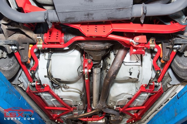
F-body cars, like the ’93-’02 Camaro and Firebird, were equipped with a solid-rear-axle (SRA) from the factory. As enthusiasts, we’ve always been told that newer cars equipped with an independent-rear-suspenion (IRS) setup are more road worthy and more capable of carving corners on the track.
However, who’s to say a late model musclecar equipped with a straight-axle and the right components, can’t compete with the latest and greatest available today? When we heard BMR Suspension was releasing an all-new Watt’s link for the fourth-gen F-body, we knew we wanted to test one out. We not only wanted to see exactly how much of an improvement we could make in a fourth-gen’s handling, but also find out if a late model car equipped with a solid-rear-axle can be just as fun, and as fast, as a newer car with an IRS setup.
Installing the new components took place at Shelley Auto Sales in Cave City, Kentucky with the help of the shop’s owner, Brian Shelley, along with technicians Wade Miller and Larry Blanton. The vehicle of choice for the installation is a ’98 WS6 Trans Am, which is owned by Courtney Shelley, Brian’s wife. The car is one of several F-bodies the Shelley family owns and does duty as both daily driver, and is now a regular competitor in autocross.
Torque-Arm SRA Set-up
It’s important to understand how the OEM F-body SRA is set up. F-body cars from ’93-’02 came equipped from the factory with a torque arm style suspension. A torque arm suspension is a SRA suspension setup similar in design to a three-link suspension. The main difference between a three-link and a torque arm suspension, is that the torque-arm setup uses an elongated arm (stamped steel from the OEM) which has mounting points between the center section of the differential and a portion of the frame towards the transmission. This setup also incorporates the use of trailing arms and a panhard bar to help control lateral movement of the rear axle.
The design of the torque-arm setup is fine for everyday street driving. However, it does have its limitations. We asked Kyle Briese from BMR about the disadvantages of the fourth-gen F-body’s suspension configuration. Briese says, “The disadvantages come from the factory panhard bar and how it’s used to locate the rearend. The rearend housing shifts side-to-side as the suspension articulates through its range of motion. However, the factory torque arm suspension used in the fourth-generation F-Body cars is actually designed very well. Many enthusiasts stick with it due to its great success.”
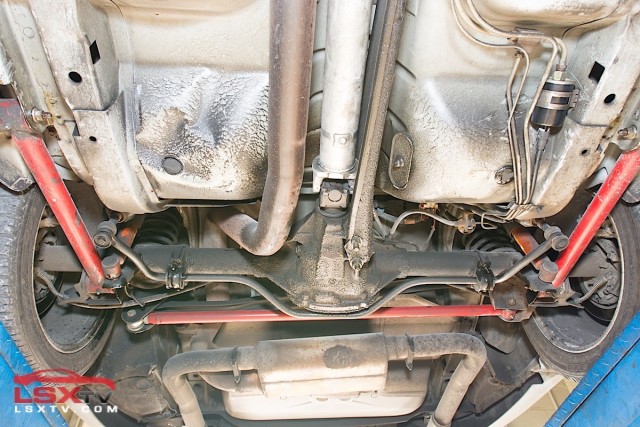
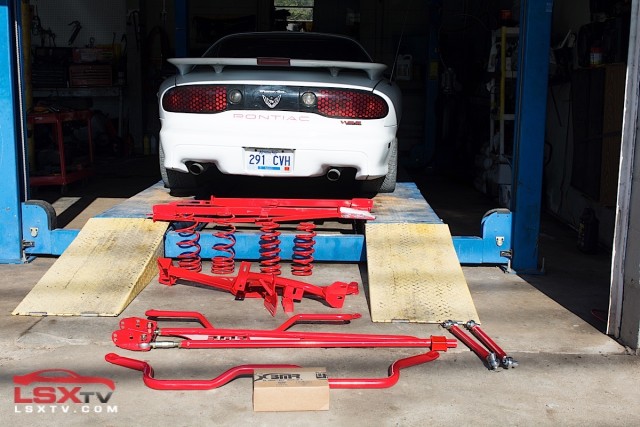
The starting point: A 1998 WS6 Trans Am with an aftermarket panhard bar and lower control arms on factory-worn suspension components.
Body Mount Watt’s Link
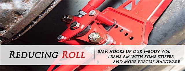
BMR’s body-mounted Watt’s link (PN WL002) is designed to fit all fourth-gen chassis, is a 100 percent bolt-on application, and is the star of our installation story. The unit does not require any cutting, welding, or permanent modification during installation, and is completely removable if desired. The factory application on the fourth-gen chassis included the use of a panhard bar to keep the axle centered, which is similar to the purpose of a Watt’s link. However, the concept of limiting lateral movement of the rear axle is where the similarities of the two end. The Watt’s link has numerous advantages over the factory panhard bar setup, as Pete Epple of BMR Suspension explains below.
“The fourth-gen F-body Watt’s link uses Teflon-lined rod ends on each of the key mounting points that are articulated,” Epple said. “The rod ends are self-lubricating, which basically means that there is no maintenance involved with them. Once the unit has been installed, there is no need to grease any of the components. The center pivot uses a Delrin bushing which is a material that has some partial self-lubricating properties. While not as efficient as Teflon, Delrin will require grease from time to time. We’ve added a grease fitting to assist in with additional lubrication.”
BMR Body Mounted Watt's Link
- Compatible with all fourth-gen F-body GM cars
- 100 percent bolt-on body mounted unit
- One-inch by two-inch rectangular steel-tubing
- Quarter-inch laser cut steel mounting plates
- Zinc-plated and heat-treated heavy-duty X-series chromoly steel and Teflon-lined rod ends
- Six roll center adjustments
- Fabricated center pivot and greasable Delrin center bushing
- Double sheer construction with double adjustable links
- Compatible with BMR or factory sway bars
- Designed and engineered for all racing applications
- Powder-coated to resist corrosion
- Manufactured in the U.S.A.
- PN WL002
“A panhard bar travels on an arc as the suspension cycles through its range of motion. This is due to a static mounting location. One mounting location is on the body side, and the other side mounts to the differential. As the differential moves through its range of motion, the panhard bar goes from its resting location, to completely centered, to above the axle housing. If you draw out the arc, it’s easy to see that the axle moves on the same arc. As the axle moves up and down, it also moves side-to-side. A Watt’s link uses two equal length rods and a center-pivot to control axle movement. The Watt’s link center-pivot is connected to the chassis, and the links are connected to the axle housing. As the suspension travels, the pivot rotates and keeps the axle centered.”
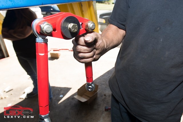
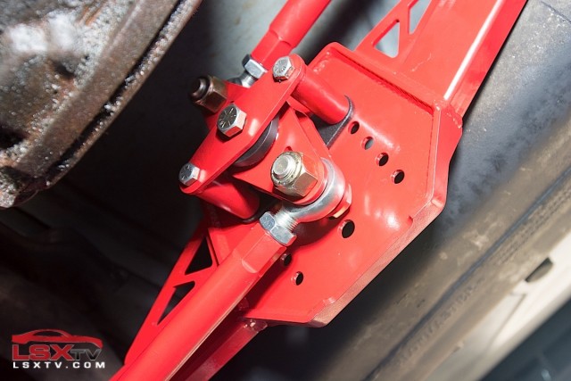
Top row left to right: BMR provides two mounting brackets which clamp over the axle tubes. The Watt's link mounting plate then attaches using the OEM panhard bar mounts. Bottom row left to right: The pivot and arms attach easily with the supplied hardware, and there is plenty of adjustment for dialing the Watt's link in for various types of car setups. For our installation we mounted the pivot to the second set of holes. BMR recommends allowing at least 3 to 4 hours of time to install the new Watt's link.
“During the development of the Watt’s Link, we measured approximately 0.280-inch of side-to-side axle movement with a panhard bar. With the Watt’s link, side-to-side axle movement was less than 0.040-inch. That’s almost 1/4-inch less. While it may not seem like a lot, that quarter-inch of dynamic movement changes where the rear wheels are in relation to the front wheels, and will dramatically effect how the car handles, even at lower speeds,” Epple continued.
Epple added that BMR designed its Watt’s link to be a bolt-on affair, requiring zero fabrication on the customer’s part. We were impressed with this design, as it allowed us to easily install the system on the car with virtually no hassle. Another useful feature is the adjustable pivot mount. This allows for fine-tuning of the Watts’ link so that owners can further dial-in rear suspension settings to their liking.
BMR also took into consideration the multitude of aftermarket exhausts systems currently available for the fourth-gen F-body. With that in mind, Epple says that the Watts link is compatible with all current aftermarket exhausts systems for the fourth-gen F-bodies.
Double-Adjustable Lower Control Arms
One of the biggest benefits of adjustable LCAs is the ability to dial in the rear-axle’s alignment. – Pete Epple, BMR Suspension
The first of those additional parts to also be installed along with the new Watt’s Link are a set of BMR chromoly lower control arms (PN MTCA003). These particular lower control arms (LCA) are a double-adjustable design and are fabricated from 4130-grade chromoly steel tubing. They are designed to be adjusted while on the car, and feature heavy-duty QA1 teflon-raced XR series spherical bushings and stainless steel spacers. The company has non-adjustable lower control arms available for enthusiasts as well. However, browse any of the F-body forums on the Internet, and you’re bound to find a heated debate regarding which one is better. Some enthusiasts claim that spherical bushings, like the ones found in the LCAs that BMR supplied, are too harsh for street duty.
Chromoly Double-Adjustable Lower Control Arms With Rod-Ends For '93-'02 GM F-Body
- Eliminates wheel hop and improves rear end traction
- Fabricated from 1.25-inch by .095-inch 4130-grade chrome-moly steel tubing
- Equipped with heavy-duty QA1 teflon raced XR-series spherical bushings
- Stainless-steel spacers for easy on-car adjustment
- Manufactured in the U.S.A.
- PN MTCA003
If you upgrade from a factory LCA with soft rubber bushings to a double-adjustable LCA with rod ends, you will definitely experience a change in noise, vibration, and harshness levels (NVH). Polyurethane bushings will not have a dramatic increase in NVH, but there can be slight change. “BMR also offers adjustable LCAs with polyurethane bushings and a heavy-duty center adjuster, which is a great middle-ground between the non-adjustable and the double-adjustable LCAs.”
Epple continues, “One of the biggest benefits of adjustable LCAs is the ability to dial in the rear axle’s alignment. Adjustable LCAs allow you to make minor wheelbase changes to separate sides, enabling you to center the wheels with the car and keep them inline with the front wheels. This is referred to as the ‘thrust angle.’ If the thrust angle is off, the rear wheels will travel in a different direction than the front wheels. This can cause erratic handling, traction issues, and premature tire wear, among other problems. On a lightly-modified car with lower power, minor changes in thrust angle aren’t as noticeable — but will still effect handing characteristics.”
Removing the rear LCAs couldn't be any simpler. Remove the two bolts which hold the LCA to the body. Replace the old component with the provided new one, then bolt everything back up.
BMR Lowering Springs Kit
To say that the purpose of BMR’s lowering springs kit (PN SP001) is to solely lower the vehicle would be a complete understatement. The springs do provide an aggressive stance which is about 1.25 inches lower than OEM on all four corners. However, the purpose of these springs goes much further than that.
BMR Lowering Spring Kit (Four Springs - 1.25-inch drop)
- Lowers all four corners approximately 1.25 inches
- Improved handling and ride-quality
- Constructed from chromoly silicone high-tensile spring material
- Cold-wound using CNC coiled method
- Stress-relieved to 750 degrees F
- Shot-peened for added durability
- Computer analyzed for accuracy
- Lifetime warranty
- Manufactured in the U.S.A.
- PN SP001
BMR offers springs various different springs designed for enthusiasts who use their vehicle for a variety of applications, whether for daily driving, drift racing, drag racing, or autocross. The springs we are using in this application are a linear spring-rate design, with front springs rated at 550 pounds, and rears rated at 160 pounds.
Since we were installing the new lowering springs from BMR, we decided to refresh the worn and tired factory dampers on Courtney's WS6, and chose to replace them with a new set of OEM dampers, as the car is a daily driver and sees a lot of city and highway streets. These parts store replacements were also all that was readily available for our install.
Four-Point Bolt-On Subframe Connectors
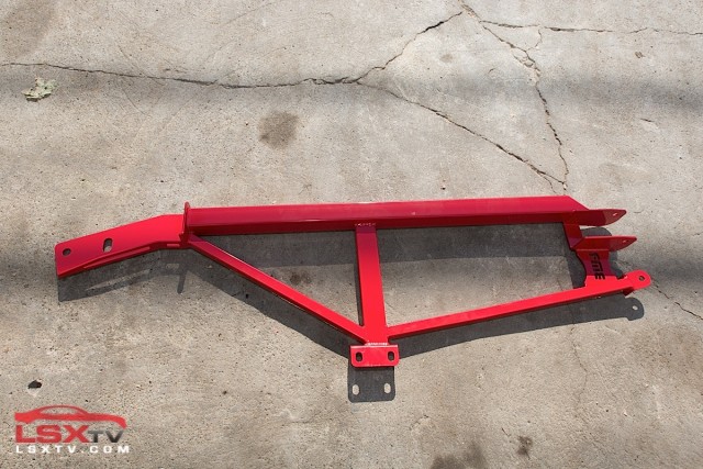
These subframe connectors (PN SFC019) are a bolt-on application, requiring no permanent modification for installation.
By removing the flex in the chassis, the energy that would have been wasted is effectively transferred through the suspension and to the ground. – Pete Epple, BMR Suspension
According to Epple, “Whether they are necessary or not really depends on three things: the application, the amount of power being made, and what the vehicle is being used for. Any time you can take deflection out of the chassis, it’s a good thing. If you have a fourth-gen Camaro or Trans Am with a few mild mods, and you go to the track a couple times a year, these subframe connectors are not absolutely necessary. If you have a built engine or a power adder with sticky tires, and the vehicle sees ample track time, it’s recommended to install this kit on the vehicle. It all comes down to chassis flex: The chassis has minor spring-like qualities to it, but it is not designed to regularly flex the way increased power will. Over time, that flex will cause damage to the chassis. Any type of deflection is wasted power, so why waste it?”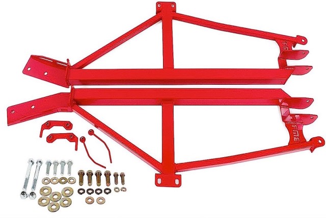
Epple continues, “Reducing chassis deflection can also change how the car handles, which is usually for the better. By removing the flex in the chassis, the energy that would have been wasted is effectively transferred through the suspension and to the ground. Less chassis deflection allows the vehicle to have a more consistent and stiffer chassis. With more consistency, you can dial the suspension in and the whole package works that much better.”
The subframe connectors are manufactured using a mix of heavy-duty square steel tubing. They are CNC-formed, laser-cut, then MIG-welded to add strength to the formed areas. The four-point connectors are designed to connect the front and rear subframe sections, as well as the LCA mounts and transmission tunnel brace.
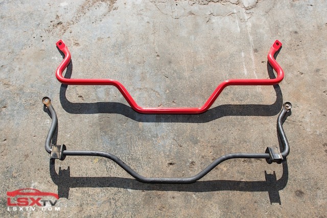
The new rear sway-bar is 25 mm in size, which is a perfect size to ensure it won’t snap our new control arms like a twig.
Front And Rear Sway Bars With End-Links Kit
The kit we received from BMR contains a 38 mm front sway-bar, 25 mm rear sway-bar, polyurethane bushing end-links, and the all of the necessary hardware included (PN SB026). The sway bars are manufactured from heavy-duty 29 mm DOM tubing, then CNC cold-formed to create a high-tolerance. The sway-bar end-links use polyurethane bushings, which are a 88 durometer rating. These low-deflection bushings are also internally fluted, which allows grease to stay in the bushings.
BMR Sway Bar Kit Including Polyurethane Bushings
- Compatible with all fourth-gen F-body cars
- Designed and engineered for all racing applications
- Decreased body roll
- Increased sway bar rate by 129 percent front, 149 percent rear
- Cold formed to resist torsional wear and fatigue
- 88 durometer polyurethane bushings included
- Zinc-plated bushing sleeves
- Powder-coated to resist corrosion
- Manufactured in the U.S.A.
- PN SB026
Since BMR offers enthusiasts the option to substitute the standard polyurethane bushings for spherical bearings, we asked Epple what the benefits of that would be. “Spherical bearings are very similar to rod-end bushings, as they are a solid bushing,” Epple said. “The differences are the way they are designed, and the load they are capable of handling. A spherical bearing is wider, and more capable of handling higher loads. Spherical bearings are pressed into the link like a traditional bushing would be installed. This means the bearing cup or end of the link needs to be machined and sized properly for the bearing. Spherical bearings make for very strong components that can handle very high amounts of horsepower and torque.”
He continues, “The downside is how much noise they transfer. Spherical bearings are solid links and will transfer much more NVH than rubber or polyurethane bushing. What is sacrificed in NVH however, is made-up for in performance. Spherical bearings will stand up to higher power levels and offer very high levels of articulation. This makes them a great choice for any high-horsepower application where bind-free suspension articulation is required.”
Installing the new sway bars is as simple as removing a few bolts. It is highly recommended to utilize the included grease for the polyurethane bushings and end-link assembly.
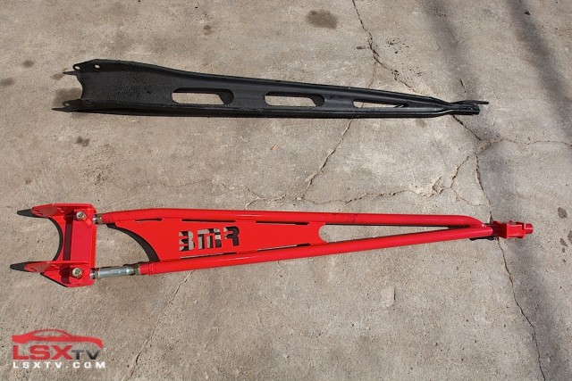
The sheer size difference and adjustability factory make this new BMR unit ideal for enthusiasts seeking to upgrade their factory torque arm.
Adjustable Torque-Arm And Relocation Crossmember
The bolt-in adjustable torque-arm (PN TA001) is a tubular design and is constructed using tubed steel and heavy-duty MIG-welded mounting plates. It’s designed to bolt-in directly into the factory location. However, we opted for BMR’s torque arm relocation crossmember (PN TCC006). This component clears the factory exhaust system, as well as all aftermarket exhausts. Since we opted for the adjustable version, the new unit is equipped with a rear-adjuster, which allows for pinion-angle adjustment. The kit also includes a low-deflection front mounted polyurethane bushing.
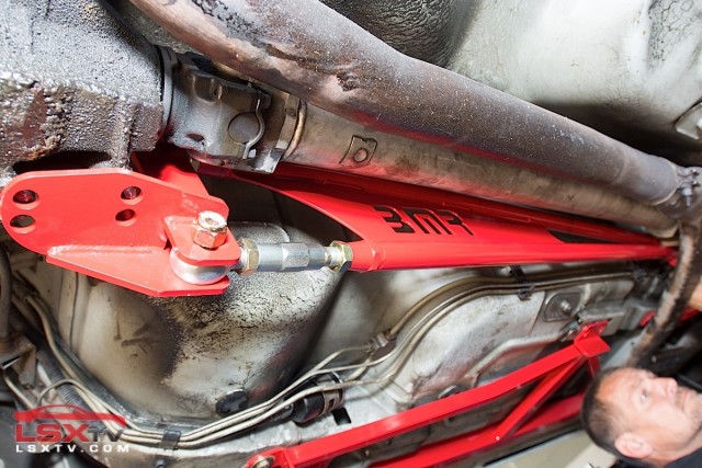 We asked Briese why it’s optimal to relocate the torque arm, and if it creates any additional rear end traction, “The factory torque-arm is mounted on the transmission tail shaft. Having the torque arm mounted on the transmission puts quite a load on the transmission housing. Throughout the years, we’ve seen enthusiasts break tailshaft housings due to the factory mounting position. This is even more prevalent on vehicles that are raced and/or make high horsepower.
Using a relocation crossmember to relocate the torque arm allows you to mount the torque arm directly to the chassis, which takes the load off the tailshaft housing. This component also has multiple mounting positions, allowing for adjustment to the instant center on the car. Instant center adjustment allows for you to experiment with how the power is transferred and fine tune the suspension for optimal traction.”
The new provided component uses stronger mounting positions thanks to the new relocation crossmember and Watt's link.
The new relocation crossmember is a dual-purpose component. It primarily replaces the factory transmission crossmember, but also integrates the front mounting position of the new torque arm. This component is constructed from heavy-wall DOM tubular steel. The mounting location serves as the adjustment point, and the kit includes all of the necessary hardware.
Street And Track Testing
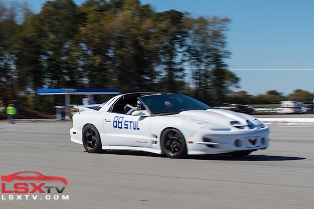
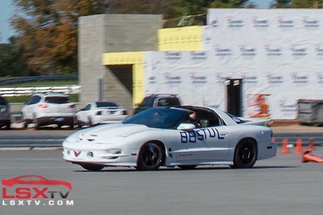
Courtney Shelley and co-driver Cindy Duncan exit a slalom and begin entering the next corner at the final 2015 Kentucky SCCA points event held at NCM Motorsports Park.
Fourth-gen F-bodies like the one we used in this project are gaining a growing following by autocross enthusiasts. When we teamed up with the Shelleys for this story, we were already dealing with a husband and wife team who spend nearly all of their autocross and track time behind the wheel of a fourth-gen. Editor Don Creason also spent time behind the wheel of the car during our test session for this story.
On the autocross, the car felt extremely balanced. It was evident that the new, stronger components were doing their job. Corner stability had notably increased. The Watt’s link had the rear of the car planted and predictable through every maneuver we put it through. In hard cornering the rear stayed stable, keeping the tires gripping and reducing the rear axle’s tendency to fight against rapid changes of direction. There was an absence of the snap-back that is sometimes associated with SRA equipped cars, especially those with worn bushings, where you can actually feel the rearend moving back to the proper position after a hard cornering maneuver. We were unable to measure lateral g-force for this test, however the seat of the pants consensus was that the car now needs better seats and harnesses to keep the driver in place since it has the grip to toss occupants around.
The car handled flat through each corner we pushed it through. Understeer was reduced significantly enough that in-spite of this car being saddled with a 200,000-plus mile engine and an automatic transmission, we were even able to induce oversteer on corner exit. Additionally corners and apexes required less of a point and squirt approach with the throttle. Rather than waiting until late in the corner to get back on the power, we were able to apply throttle much earlier before the corner exit, making for a faster corner exit and thus decreasing our lap times. This change was due entirely to the Watt’s link keeping the rear axle in line and flat.
Oversteer was easier enough to induce with the settings we selected that two of the four drivers we used for testing even spun the car due to this during one of their test laps, which we largely blamed on their expectation (based on past experience) that the car would understeer. Having a complete suspension system also made the car more predictable and easier to drive at the limits of its tires and operator.
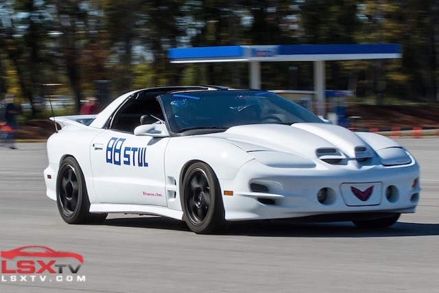 We also noticed a lack of wheel-hop during hard braking on the autocross. Fourth-gen cars are notorious for this as the bushings in the rear suspension and OEM torque arm wear and deteriorate. During extreme braking events the suspension bushings simply can not keep up. We’ve driven fourth-gens where this condition was so bad we were checking the mirror to make sure we hadn’t left parts on the course. Thanks to the spherical bushings and design of the BMR components we experienced zero wheelhop during deceleration and acceleration.
During normal street cruising the car felt comfortable and confident without feeling harsh. The lowering springs provide an excellent ride quality without any bumpsteer or additional noise. The car also feels a lot more confident, even at lower speeds. Both Brian and Courtney Shelley haven’t reported any major changes in NVH, either. This is great news, as some of the components supplied by BMR use a mixture of polyurethane, Delrin, and spherical bushings.
Over the winter the Shelley’s will be swapping out the automatic transmission for a manual unit, and looking at other upgrades for this particular F-body. The car may even head out to some bigger track and autocross events. Thanks to the new chassis parts from BMR Suspension and the Shelley’s experience behind the wheel, this equipped Trans Am should be a terror at autocross events in the 2016 season.


