The LS is officially 20 years old now, yet it seems something new comes along almost daily with regard to performance-building these engines. On the traditional small-block Chevy, everyone learned at a tender age about setting lash, whether it was clearance on a solid lifter cam or preloading the lifters for a hydraulic cam. One of the “advantages” of the LS engine was that this process of setting lash became unnecessary. All LS engines were designed around the net lash system. But that turns out to have both positive and negative ramifications.
Here’s how it works. As we all know, assembling the valvetrain for an LS engine is downright simple. With the cam and lifters in place, you slide in the pushrods, install the rockers and just bolt everything down. GM calls this the net lash system and when all the parts are stock, this system works very well. With a stock camshaft, lifter, and pushrod, the system is designed to depress the piston inside the lifter by roughly 0.050-inch. The total piston travel in the lifter is roughly 0.120- to 0.150-inch which places the lifter roughly at mid-travel.
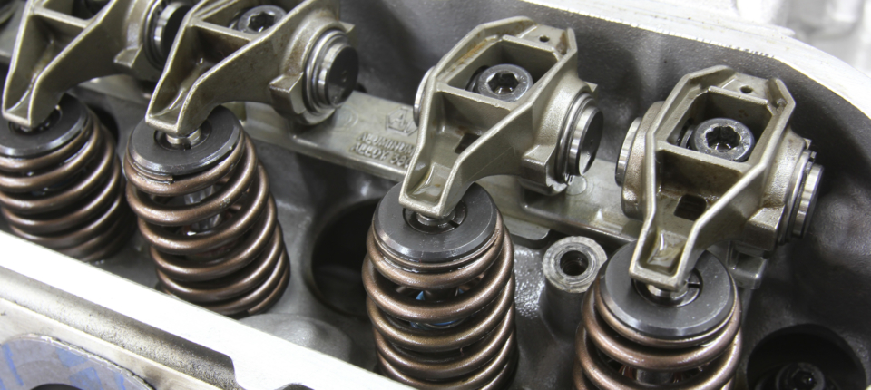
An LS valvetrain is configured differently from its older Gen I small- and big-block cousins as it does not offer an adjustable valvetrain. Tightening the rocker arm in place automatically establishes the lifter preload based on the pushrod length.
Why Does It Matter?
Before we get into how to check LS lifter preload, this might be a good place to investigate why lifter preload is important. Most cam manufacturers want the lifter plunger down roughly 0.050-inch into the lifter body for several reasons. It compensates for engine expansion as the engine approaches its normalized temperature. Essentially these lifters use the volume of oil underneath the piston much like a hydraulic accumulator.
For decades, engine builders have preloaded the piston ever-so-slightly. The standard spec was a quarter-turn on the adjuster on a 7/16-inch x 20 rocker stud. With 20 threads per inch, one full turn would be 0.050-inch so a quarter-turn would be roughly 0.012-inch. The theory was that this limited the amount of distance the little piston would travel if (or when) it “pumped up” when the valvespring lost control of the valve causing valvetrain separation.
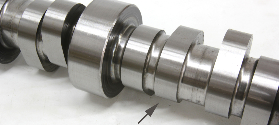
To check lifter preload, that valve has to be on the base circle of the lobe (arrow). The base circle is the round portion of the lobe. Performance camshafts often increase lobe lift by reducing the diameter of the base circle. A reduction in base circle on an LS engine reduces the lifter preload by the same amount.
The alternate approach was to preload the piston to just 0.020-inch from the bottom of the piston travel in the lifter. The theory here was to limit the amount of oil underneath the piston and therefore limit the amount of entrapped air in the oil that will compress and cost valve lift at high RPM. For street engines and especially the LS engine family, setting the preload roughly in the middle of lifter travel is not a bad way to go. As an example, Katech, the Detroit-based engine builder, recommends 0.070-inch while others like Brian Tooley Racing recommend 0.100-inch for LS7-style lifters. In these cases, they are attempting to minimize the height of the hydraulic fluid under the lifter piston.
The reason for this is an attempt to minimize the volume of oil under the piston. The idea is that any amount of oil under the piston will contain a small amount of air. By minimizing the amount of oil, this also reduces the amount of air that can be compressed.

To find an intake lobe’s base circle, slowly turn the engine over and watch the pushrod side of the exhaust rocker arm. When the exhaust rocker begins to move (foreground), this positions the intake lobe on its base circle. This allows you to loosen the intake rocker and check its preload.
For LS engines, the standard recommendation has been between one-half and one full turn from when the rocker first eliminates all the clearance as the bolt is tightened. We’ll save you the math conversion but the 8 x 1.25 thread pitch metric bolt is roughly equivalent to 20 threads per inch, so one full turn of adjustment would be equal to 0.050-inch of lifter preload and three-quarters-of-a-turn would be just under 0.040-inch. For LS street engines, the approach is to create the preload in the middle of the piston travel, somewhere approaching 0.040- and 0.050-inch, so three-quarters-turn is right where you want to be.
The high-tech approach (versus the three-quarter-turn technique), is to use an adjustable pushrod length checker. We like the Comp Cams tool that uses threads to increase or decrease its length. Each revolution in the adjustable pushrod equals a 0.050-inch change in length, making it easy to establish pushrod length.
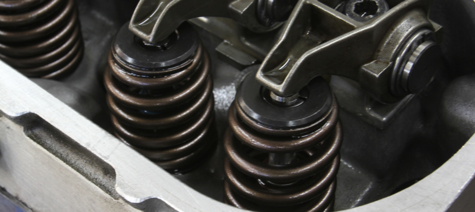
To establish the base circle for the exhaust lobe, rotate the engine and stop when the intake rocker is nearly closed. This will place the exhaust lobe on its base circle. The easiest way to remember this is Exhaust-Opening (EO) and Intake Closing (IC) or EO-IC.
The Process Of Checking
Here’s how to check the preload. With an assembled engine make sure the spark plugs are all removed to make it easy to turn the engine over by hand. We’ll start by checking the intake on cylinder number one. We must first put the intake cam lobe on its base circle. Do that by inserting a pushrod into the number-one exhaust lifter location and turn the engine until the exhaust pushrod just starts to rise. This positions the intake lobe on its base circle.
Since the LS stock pushrod length is 7.400-inch, we’ll set the pushrod around 7.300-inch to start with. Place the adjustable pushrod on the lifter, mount the rocker, and slowly tighten the bolt while checking for contact between the pushrod and the rocker. More than likely, with the bolt tight, there will be clearance between the pushrod and the rocker arm. Remove the rocker and adjust the pushrod length until there is zero clearance between the rocker and the pushrod.
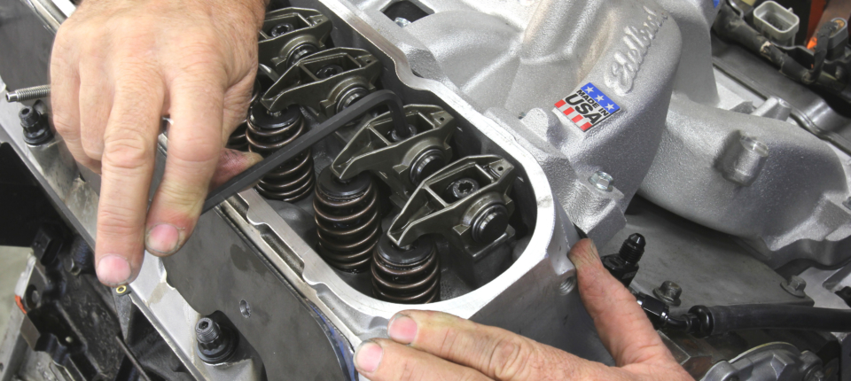
The quickest way to check preload is to set the rocker at zero lash with the lobe on the base circle. Then keep track of the rotation until the bolt tightens. The ideal lash number is three-quarters of a turn. One full turn or more will preload the lifter piston deeper while less than half a turn may be too little especially for an all-aluminum engine.
Next, remove the pushrod and count the revolutions back to its base length. Each revolution is worth 0.050-inch so if the count is 10 turns (from the base length of 6.80-inches), that adds 0.500-inch to the original length of the pushrod. In this case, this puts the pushrod length at 7.300-inch.
Now all we have to do is add the desired amount of lifter preload to that 7.300-inch length. If we want 0.050-inch of preload, then the proper pushrod length for the intake side of the engine will be 7.350-inch. Most pushrod companies sell pushrods in 0.050-inch steps. Both Comp Cams and Trend Performance also stock 5/16-inch, heavy-duty (0.080-inch wall thickness) pushrods in 0.025-inch length steps in the lengths for the LS engine. If you desire a custom length in between these – that is also available.
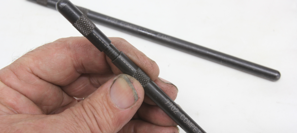
Comp makes these nice adjustable pushrods that can be used to accurately determine the pushrod length needed. Each turn of the adjustment is equal to 0.050-inch created when the marks line up. Do not use these checking pushrods against spring pressure – they will bend and destroy the tool.
All of this is relatively simple, but we also should address short-travel lifters. These are relatively new to the industry. Earlier we touched on what can happen if the valvespring loses control over the valve and assembly. Potentially, this can occur when the pushrod flexes enough to launch the lifter off the nose of the cam, causing valvetrain separation. When this happens, oil pressure will instantly push the hydraulic lifter piston to the top of its travel. This will extend the internal piston and hold the valve open off the seat by the amount of the preload. This is not good.
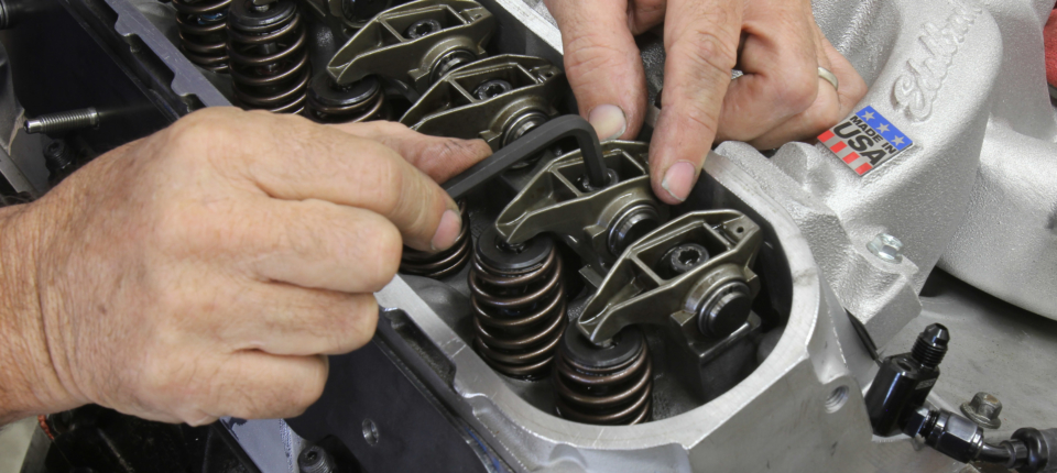
With the intake valve on the base circle, install the checking pushrod and lengthen it until all the clearance is removed from the system. Determine the length of the pushrod and then add the amount of preload required. A typical LS engine with a performance cam will need a pushrod between 7.350- and 7.400-inch.
If we minimize the lifter piston travel distance to roughly half of stock—or 0.050-inch—with a short-travel lifter, this accomplishes two things. First, it minimizes the volume of oil underneath the hydraulic piston and the air in the oil that could cause a loss of valve lift. Secondly, this short travel would demand a reduced preload – back to our earlier quarter-turn example of about 0.010- to 0.015-inch of preload. Comp makes a set of stock replacement-style, short-travel hydraulic roller lifters for the LS family of engines – we’ve included their part number in the attached chart above.
The End Of The Road
With this short explanation, you now know quite a bit more about the valvetrain dynamics and lifter preload so that the next time a question comes up, you’ll know how it all works and how to best address the issue.


